69
RB SERIES ENGINEERING GUIDE
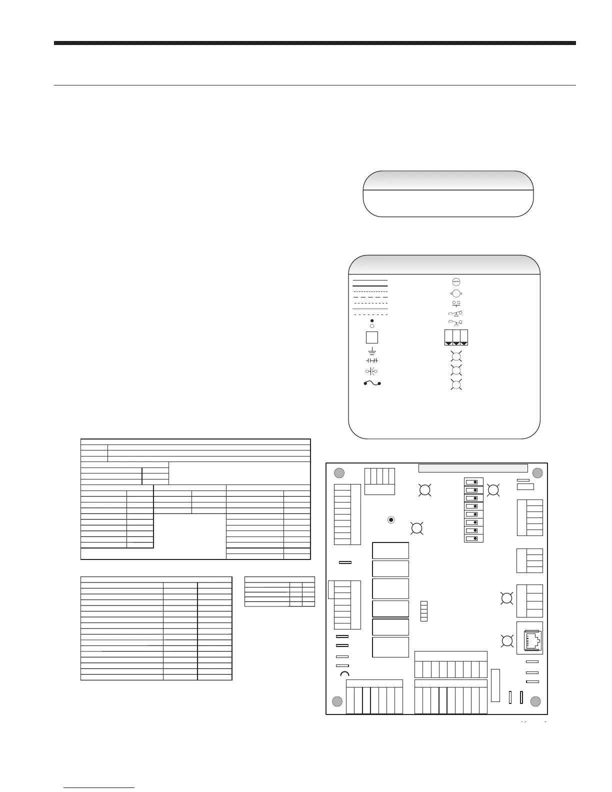
Thermistor
Relay Coil
Switch - Condensate Overflow
Switch - High pressure
Switch - Low pressure
Polarized connector
Factory Low Voltage Wiring
Factory Line Voltage Wiring
Field Low Voltage Wiring
Field Line Voltage Wiring
Optional Block
DC Voltage PCB Traces
Internal Junction
Quick Connect Terminal
Field Wiring Lug
Ground
Relay Contacts – N.O., N.C.
Field Zone Sensor Wiring
Legend
L1
Capacitor
T
1
2
3
CC – Compressor Contactor
CO – Condensate Overflow Sensor
ES – Emergency Shutdown
HP – High Pressure Switch
LP – Low Pressure Switch
FD – Freeze Detection Sensor
F1 – Fuse
1 – Optional, factory installed unit mounted disconnect.
2 – Swap blue and red leads for 208V operation.
3 – Optional, factory installed internal isolation valve.
Notes:
97P817-12
01/14/2013
Slow Flash
Fast Flash
Flash Code
Status LED (LED1, Green)
Configuration LED (LED2, Yellow)
Fault LED (LED3, Red)
Status LED (LED1, Green)
Normal Mode
Control is Non-Functional
Test Mode
Lockout Active
Dehumidification Mode
Reserved
Reserved
Load Shed
ESD
1 second on and 1 second off
Random Start Delay
Fast Flash
OFF
ON
Slow Flash
Fast Flash
Flash Code 2
Flash Code 3
Flash Code 6
Flash Code 4
Flash Code 5
Aurora LED Flash Codes
100 milliseconds on and 100 milliseconds off
100 milliseconds on and 400 milliseconds off with a 2 second pause before repeating
Reserved
Flash Code 7
Configuration LED (LED2, Yellow)
Fault LED (LED3, Red)
Fast Flash
Fast Flash
No Software Overide Flash ECM Setting
DIP Switch Overide Slow Flash
Normal Mode
Input Fault Lockout
High Pressure Lockout
Low Pressure Lockout
Low Water Coil Limit Lockout - FP1
Low Air Coil Limit Lockout - FP2
Reserved
Condensate Overflow Lockout
Over/Under Voltage Shutdown
Reserved
Reserved
Air/Water Coil Limit Sensor Error
Flash Code 1
OFF
Flash Code 2
Flash Code 3
Flash Code 4
Flash Code 5
Flash Code 8
Flash Code 6
Flash Code 7
Flash Code 9
Flash Code 10
Flash Code 11
ECM Configure Mode Fast Flash
Reset Configure Mode Off
Fuse
SW1 – Push button
SW2 – DIP package 8 position
RB – Blower Relay
RV – Reversing Valve Coil
Accessory Relay
Cycle with Blower
Cycle with Compressor
Water Valve Slow Open
Outdoor Air Damper
SW2-4
SW2-5
On
On
Off
Off
On
Off
Off On
Operation
Light Emitting Diode - Green
G
Light Emitting Diode - Yellow
Y
Light Emitting Diode - Red
R
Event
Normal Mode
Test Mode
Random Start Delay
Compressor On Delay
Compressor Minimum On Time
Compressor Short Cycle Delay
Blower Off Delay
Fault Recognition Delay – High Pressure
Start-Up Bypass – Low Pressure
Fault Recognition Delay – Low Pressure
Start-Up Bypass – Low Water/Air Coil Limit
Fault Recognition Delay – Low Water/Air Coil Limit
Fault Recognition Delay – Condensate Overflow
Thermostat Call Recognition Time
Auxiliary Heat Staging Delay
Emergency Heat Staging Delay
Less than 1 second
5 to 80 seconds 1 second
5 seconds < 1 second
30 seconds 2 seconds
Less than 1 second
2 minutes 5 seconds
4 minutes 15 seconds
2 minutes
2 minutes
30 seconds
30 seconds 30 seconds
30 seconds
30 seconds
30 seconds
30 seconds
30 seconds
2 seconds 2 seconds
5 minutes
2 minutes
20 seconds
7.5 seconds
Aurora Timing Events
Reheat Delay
30 seconds 30 seconds
Water Valve Slow Open Delay
90 seconds 90 seconds
CC2
EH1
Factory
Fault
ALG
ALM
LS
ES
ACC c
Status
AURORA BASE
CONTROL™
RV – K1
CC2
CC – K2
CC Hi – K3
Fan – K4
Alarm – K5
Acc – K6
ACC no
ACC nc
O/B
C
R
LO
G
Y1
Y2
W
DH
3A-Fuse
O/B
C
R
LO
G
Y1
Y2
W
DH
LO
G
HI
CCG
CC
FG
F
R
HP
HP
LP
FP2
FP2
FP1
REV
REV
CFM
PWM
ECM PWM
Factory
Factory Fan Connection
RR
CC
C
C
R
(-)
(+)
RS 485
EH2
C
EH1
C
CO
(+)
(-)
R
C
RS485 Exp
Factory
Com1
Com2
Config
G
G
G
YR
SW1 Test
FP1 – 15
o
F/30
o
F
JW2 -
Alarm
P11
P5
P2
P1
P8
P7
P9
P6
P3
SW2
P13
P4
FP2 – 15
o
F/30
o
F
RV – B/O
ACC – Dip 4
ACC – Dip 5
CC – Dual/Single
L – Pulse/Continuous
Reheat/Normal
Factory Use
Field ConnectionsField Connections
C
LP
FP1
F
CC
G
Y1
1
2
3
4
5
6
7
8
Off
On
N/A
RS485 NET
LED3
LED2LED1
Wiring Schematics cont
Aurora Base Control 208-230-265/60/1 with PSC