71
RB SERIES ENGINEERING GUIDE
Aurora Base Control 460/60/3 with ECM Motor
1 – Optional, factory installed unit mounted disconnect.
2 – Optional, factory installed internal isolation valve.
3 – Optional, fac tory installed phas e guard
4 – Optional, factory installed phase guard. The yellow transformer wire
shall be connected directly to the CPU board, if this option is not installed.
Notes:
Slow Flash
Fast Flash
Flash Code
Status LED (LED1, Green)
Conf igur ation LED (LE D2, Yellow)
Faul t LED (LED3, Red)
Status LED (LED1, Green)
Normal Mode
Cont rol is Non-Funct ional
Tes t Mode
Lockout Active
Dehumidification Mode
Reserved
Reserved
Load Shed
ESD
1 second on and 1 second off
Ra nd om S tart Del ay
Fas t Fl ash
OF F
ON
Slow Flash
Fas t Fl ash
Fl ash Code 2
Fl ash Code 3
Flash Code 6
Flash Code 4
Flash Code 5
Auro ra LED Flash Codes
100 milliseconds on and 100 milliseconds off
100 milliseconds on and 400 m illiseconds of f with a 2 second pause before repe ating
Reserved
Flash Code 7
Configuration LED (LED2, Yellow) Fault LED (LED3, Red)
Fas t Fl ash
Fas t Fl ash
No Software Overide Flash ECM Setting
DIP Switch Overide Slow Flash
Normal Mode
Input Fault Lockout
High Pressure Lockout
Low Pressure Lockout
Low Water Coil Limit Lockout - FP1
Low Air Coil Limit Lockout - FP2
Reserved
Condensate Overflow Lockout
Over/Under Volt age Shutdown
Reserved
Reserved
Air/Water Coil Limit Sensor Error
Flash Code 1
OF F
Flash Code 2
Flash Code 3
Flash Code 4
Flash Code 5
Flash Code 8
Flash Code 6
Flash Code 7
Flash Code 9
Flash Code 10
Flash Code 11
ECM Configu re Mod e Fas t Fl ash
Reset Configure Mode Off
Accessor y Relay
Cycle wit h Blower
Cycl e with Compressor
Water Valve Slow Open
Outdoor Air Damper
SW2-4
SW2-5
On On
Of f
Of f
On Of f
Of f On
Operation
Event
Normal Mode
Test Mode
Random Start Delay
Compressor O n Delay
Compressor Minimum On Time
Compressor Short Cycl e Delay
Blower Off Delay
Fault Recognition Delay – High Pressure
Start-Up Bypass – Low Pressure
Fault Recognition Delay – Low Pressure
Start-Up Bypass – Low Water/Air Coil Limit
Faul t Recogn itio n Delay – Low Water/Air Coil Limit
Fault Recognitio n Delay – Condensate Overflow
Thermos tat Call Recognit ion Tim e
Auxi liary Heat Staging Delay
Emergency Heat S tagi ng Dela y
Less than 1 second
5 to 80 seconds 1 second
5 seconds < 1 second
30 seconds 2 seconds
Less t han 1 second
2 minutes 5 seconds
4 minutes 15 seconds
2 minutes
2 minutes
30 seconds
30 seconds 30 seconds
30 seconds
30 seconds
30 seconds
30 seconds
30 seconds
2 seconds 2 seconds
5 minutes
2 minutes
20 seconds
7.5 seconds
Aurora T imi ng Events
Reheat Delay
30 seconds 30 seconds
Water Valve Slow Open Delay
90 seconds 90 seconds
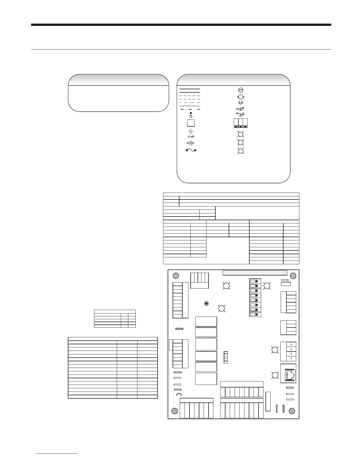
Ther mis tor
Relay Coi l
Switch - Condensate Overflow
Switch - High pressure
Switch - Low pressure
Polarized connec tor
Factory Low Volt age Wiring
Factory Line Vol tage Wiring
Field Low Voltage Wiring
Field Li ne Voltage Wi ri ng
Optional Block
DC Voltage PCB T races
Internal Junction
Qui ck Con nect Terminal
Field W iring Lug
Ground
Relay Con tacts – N.O., N.C.
Field Z one Sensor Wi ri ng
Legend
L1
Capacitor
T
1
2
3
CC – Compressor Contactor
CO – Condensate Overfl ow Sensor
ES – Emergency Shutdown
HP – High Pressure Switch
LP – Low Pressure Switch
FD – Freeze De tecti on Sensor
F1 – Fuse
Fus e
Light Emit ti ng Diode - Green
G
Light Emit ti ng Diode - Yellow
Y
Light Emit ti ng Diode - Red
R
SW1 – Push button
SW2 – DIP package 8 position
RB – Blower Relay
RV – Reversi ng Valve Coi l
PGM – Phase Guard Monitor
RH – Reheat V alve Coi l
CC2
EH1
Fac tory
Faul t
ALG
ALM
LS
ES
ACC c
Status
AURORA BASE
CONTROL™
RV – K1
CC2
CC – K2
CC Hi – K3
Fan – K4
Alarm – K5
Acc – K6
ACC no
ACC nc
O/B
C
R
LO
G
Y1
Y2
W
DH
3A-Fuse
O/B
C
R
LO
G
Y1
Y2
W
DH
LO
G
HI
CCG
CC
FG
F
R
HP
HP
LP
FP2
FP2
FP1
REV
REV
CFM
PWM
ECM PWM
Fac tory
Factory Fan Connection
RR
CC
C
RS 485
EH2
C
EH1
C
CO
(+)
(-)
R
C
RS485 Exp
Fac tory
Com1
Com2
Config
G
G
G
YR
SW1 Test
FP1 – 15
o
F/30
o
F
JW2 -
Alarm
P11
P5
P2
P1
P8
P7
P9
P6
P3
SW2
P13
P4
FP2 – 15
o
F/30
o
F
RV – B/O
ACC – Dip 4
ACC – Dip 5
CC – Dual/Single
L – Pulse/Continuous
Reheat/Normal
Factory Use
Field Connect ionsField Connect ions
C
LP
FP1
F
CC
G
Y1
1
2
3
4
5
6
7
8
Of f
On
N/A
RS485 NET
LED3
LED2LED1
Wiring Schematics cont.