WARNING
PROPANE AND HIGH ALTITUDE CONVERSION
KITS
The installer must take every precaution to insure
that the furnace has been converted to the proper
gas orifice size when the furnace is installed. It is
very important to choose the correct kit and/or gas
orifices for the altitude and the type of gas for which
the furnace is being installed.
High altitude conversions are required in order for
the appliance to satisfactory meet those applications.
Only use natural gas in furnaces designed for natural
gas. Only use propane (LP) gas for furnaces that have
been properly converted to use propane (LP) gas. Do
not use this furnace with butane gas.
Incorrect gas orifices or a furnace that has been
improperly converted creates an extremely dangerous
condition that results in premature heat exchanger
failure, excessive sooting, high levels of carbon
monoxide, personal injury, property damage, and
potential for fire hazard and/or death.
An authorized distributor or dealer must make all gas
conversions. In Canada, a certified conversion station
or other qualified agency, using factory specified and/
or approved parts, must perform the conversion.
Do not attempt to drill out any orifices to obtain
the proper orifice size. Drilling out a gas orifice will
cause misalignment of the burner flames, causing
premature heat exchanger burnout, high levels of
carbon monoxide, excessive sooting, a fire hazard,
personal injury, property damage and/or death.
High altitude pressure switch
conversion
For installation where the altitude is less than 5,000
ft (1,524 m), it is not required to change the pressure
switch unless you are in an area subject to low pressure
inversions.
Electric power
Electric power connections
Field wiring to the unit must be grounded. Electric wires
that are field-installed must conform to the temperature
limitation for 63°F (35°C) rise wire when installed in
accordance with instructions. See Table 5 for specific
furnace electrical data.
CAUTION
Use copper conductors only.
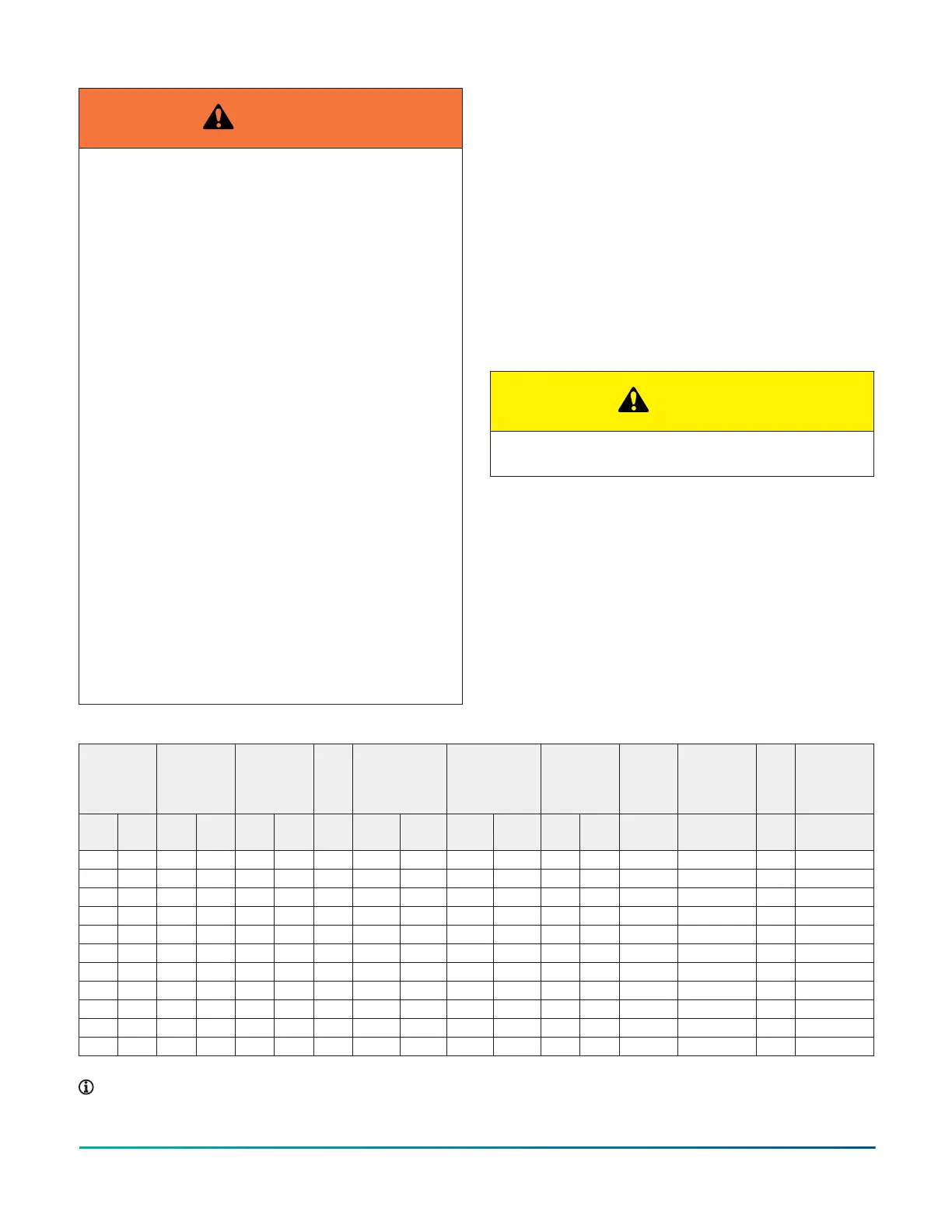
Table 5: Ratings and Physical/Electrical Data
Input Output Nominal
airflow
AFUE Air
temperature
rise
Maximum
outlet air
temperature
Blower Blower
size
Recommen
ded fuse
or circuit
breaker
Total
unit
Gas pipe
connection,
NPT
MBH kW MBH kW CFM
m
3
/
min
% ºF ºC ºF ºC HP A in. A A in.
40 11.7 32 9.4 1200 34.0 80 20–50 11–28 190 88 1/2 6.4 11 x 8 15 8.2 1/2
60 17.6 48 14.1 1200 34.0 80 30–60 17–33 190 88 1/2 6.4 11 x 8 15 8.2 1/2
80 23.5 64 18.8 1200 34.0 80 35–65 19–36 190 88 1/2 6.4 11 x 8 15 8.7 1/2
80 23.5 64 18.8 1600 45.3 80 30–60 17–33 190 88 1/2 6.4 11 x 10 15 8.8 1/2
80 23.5 64 18.8 2000 56.6 80 25–55 14–31 190 88 1 11.5 11 x 11 20 13.8 1/2
100 29.3 80 23.4 1200 34.0 80 40–70 22–39 190 88 1/2 6.4 11 x 8 15 8.7 1/2
100 29.3 80 23.4 1600 45.3 80 40–70 22–39 190 88 3/4 8.8 11 x 10 15 11.1 1/2
100 29.3 80 23.4 2000 56.6 80 25–55 14–31 190 88 1 11.5 11 x 11 20 13.8 1/2
120 33.7 96 26.9 1600 45.3 80 40–70 22–39 190 88 3/4 8.8 11 x 10 15 11.1 1/2
120 33.7 96 26.9 2000 56.6 80 35–65 19–36 190 88 1 11.5 11 x 11 20 13.7 1/2
130 38.1 104 30.5 2000 56.6 80 35–65 19–36 190 88 1 11.5 11 x 11 20 13.7 1/2
Note:
• Annual Fuel Utilization Efficiency (AFUE) numbers are determined in accordance with DOE test procedures.
Installation Manual: RL18 Single-Stage Standard ECM Residential Gas Furnaces (Non-condensing Multi-position Standard
Low NOx)
19
Johnson Controls Ducted Systems