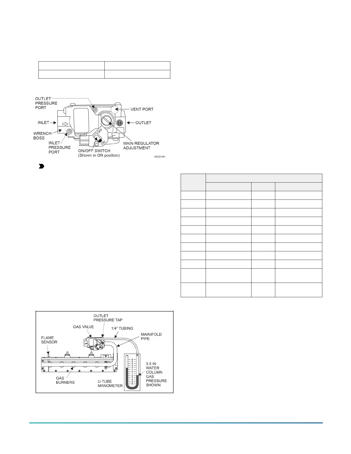
4. Adjust manifold pressure by adjusting gas valve
regulator screw for the appropriate gas per the
following.
Table 11: Nominal manifold pressure
Natural gas 3.5 in. W.C. (0.87 kPa)
Propane (LP) gas 10.0 in. W.C. (2.488 kPa)
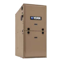
Figure 27: Gas valve
Important: If gas valve regulator is turned in
(clockwise), manifold pressure is increased.
If screw is turned out (counter clockwise),
manifold pressure will decrease.
5. After the manifold pressure has been adjusted, re-
calculate the furnace input to make sure you have not
exceeded the specified input on the rating plate. See
Calculating the furnace input (natural gas).
6. Once the correct BTU (kW) input has been
established, turn the gas valve to OFF and turn the
electrical supply switch to OFF; then remove the
flexible tubing from the gas valve pressure tap and
tighten the pressure tap plug using the 3/32 in. (2.4
mm) hex head wrench.
7. Turn the electrical and gas supplies back on, and
with the burners in operation, check for gas leakage
around the gas valve pressure port using an approved
non-corrosive gas leak detection fluid, or other non-
flammable leak detection methods.
Figure 28: Reading gas pressure
Airflow settings
Cooling airflow settings
This unit is equipped with a five-speed blower motor.
Select the required cooling airflow by connecting
the required motor speed tap wire to the HI COOL
terminal on the control board. Select the speed to deliver
approximately 350 CFM to 400 CFM per ton of AC cooling
capacity. Use of airflow outside of this range may result in
diminished air conditioning performance and may result
in lower overall energy efficiency and higher electric utility
bills. See Table 12 for default cooling blower settings.
Continuous fan airflow default settings
The default blower speed for continuous fan operation is
LOW speed. The continuous fan speed is set at the factory
to the default continuous fan blower speed.
The default position is with the LOW speed motor wire
on the G terminal. In certain circumstances, it may be
necessary to move the continuous fan speed to a different
speed. However, doing so results in higher than normal
electrical energy usage and electric utility bills.
Table 12: Default blower speeds
Default blower speedsModel
number
Heat Cool Continuous fan
040A12 Low (1) High (5) Medium low (2)
060A12 Medium low (2) High (5) Low (1)
080B12 Medium (3) High (5) Low (1)
080C16 Medium (3) High (5) Low (1)
080C20 Medium (3) High (5) Low (1)
100B12 Medium (3) High (5) Low (1)
100C16 Medium low (2) High (5) Low (1)
100C20 Medium (3) High (5) Low (1)
120C16 Medium low (2) High (5) Low (1)
120C20 High (5) Medium
high (4)
Low (1)
130D20 High (5) Medium
high (4)
Low (1)
Gas heating airflow default setting
This unit is equipped with a five-speed blower motor. The
heating blower speed is set at the factory to the default
blower speed, which is the blower speed that delivers
the correct airflow for proper heating operation in most
applications. The default heating blower speed for each
model is shown in Table 12. Use of a heating speed other
than the default heating blower speed may result in
reduced energy efficiency and higher electric utility bills.
In certain circumstances, it may be necessary to move
the heating blower speed to a different motor speed
tap. Not all five motor speeds are appropriate for gas
heating operation. The use of heating airflow on a speed
other than the default speed results in diminished heating
performance and may cause the furnace temperature
limit controls to shut down the furnace.
Installation Manual: RL18 Single-Stage Standard ECM Residential Gas Furnaces (Non-condensing Multi-position Standard
Low NOx)
31
Johnson Controls Ducted Systems