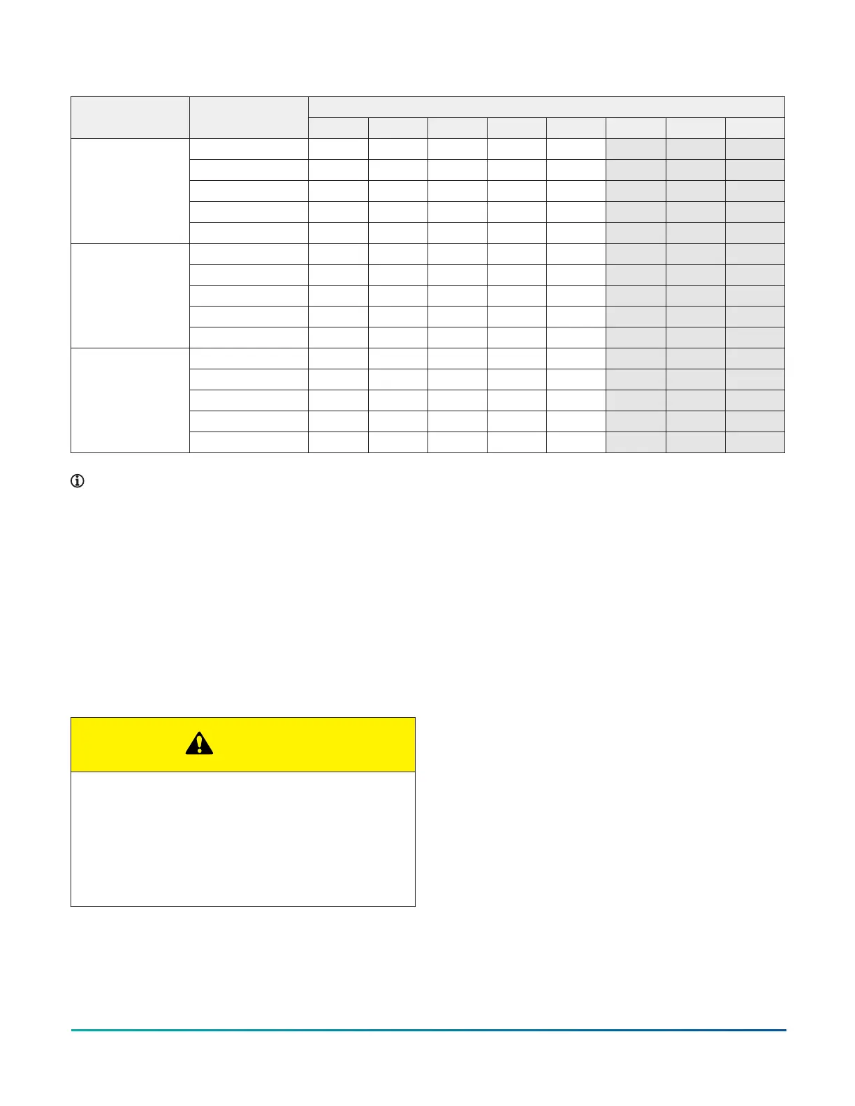
Table 14: Blower performance CFM - any position (without filter)
Airflow data (SCFM) external static pressure (in. W.C.)Model Speed
0.1 0.2 0.3 0.4 0.5 0.6 0.7 0.8
High 2050 2025 1975 1950 1925 1900 1850 1800
Medium High 1850 1800 1775 1750 1700 1675 1625 1600
Medium 1700 1675 1650 1600 1550 1525 1475 1450
Medium Low 1475 1425 1400 1350 1325 1275 1250 1200
120C16
Low 1175 1125 1075 1025 1000 950 900 875
High 2000 1925 1875 1825 1775 1725 1675 1625
Medium High 1850 1775 1725 1675 1600 1550 1500 1450
Medium 1700 1625 1575 1500 1450 1400 1325 1275
Medium Low 1475 1400 1350 1275 1225 1175 1100 1050
120C20
Low 1250 1175 1100 1025 950 875 800 725
High 2100 2050 2000 1975 1925 1875 1850 1800
Medium High 1925 1875 1825 1800 1775 1725 1675 1650
Medium 1750 1725 1675 1625 1600 1550 1500 1475
Medium Low 1625 1575 1525 1475 1425 1375 1325 1300
130D20
Low 1325 1250 1200 1150 1075 1025 950 900
Note:
• Airflow is expressed in standard cubic feet per minute (SCFM).
• Motor voltage is at 115 V.
• Not all speeds are recommended for use as heating speeds.
Safety controls
Control circuit fuse
A 3 A fuse is provided on the control circuit board to
protect the 24 V transformer from overload caused by
control circuit wiring errors. This is an ATO 3 automotive-
type fuse and is located on the control board.
Blower door safety switch
CAUTION
Main power to the unit must still be interrupted at the
main power disconnect switch before any service
or repair work is to be done to the unit. Do not rely
upon the interlock switch as a main power
disconnect.
Blower and burner must never be operated without
the blower panel in place.
This unit is equipped with an electrical interlock switch
mounted in the blower compartment. This switch
interrupts all power at the unit when the panel covering
the blower compartment is removed.
Electrical supply to this unit is dependent upon the panel
that covers the blower compartment being in place and
correctly positioned.
Rollout switch controls
These controls are mounted on the burner assembly.
If the temperature in the area surrounding burner
exceeds its set point, the gas valve is de-energized. The
operation of this control indicates a malfunction in the
combustion air blower, heat exchanger, or a blocked vent
pipe connection. Corrective action is required. These are
manual reset controls that must be reset before operation
can continue.
Pressure switches
This furnace is supplied with a pressure switch, which
monitors the flow through the combustion air/vent
piping and condensate drain system. This switch de-
energizes the gas valve if any of the following conditions
are present:
• Blockage of vent piping or terminal
• Failure of combustion air blower motor
Installation Manual: RL18 Single-Stage Standard ECM Residential Gas Furnaces (Non-condensing Multi-position Standard
Low NOx)
34
Johnson Controls Ducted Systems