Dampers, louvers and grilles (Canada only)
The blocking effects of louvers, grilles and screens must
be given consideration in calculating free area. If the free
area of a specific louver or grille is not known, see Table 6,
to estimate free area.
Table 6: Estimated free area
Wood or metal
Louvers or grilles
Wood 20-25%
1
Metal 60-70%
1
Screens
2
1/4 in. (6.4 mm) mesh or
larger 100%
Note:
a. Do not use less than 1/4 in. (6.4 mm) mesh.
b. The free area of louvers and grille varies
widely; the installer must follow louver or grille
manufacturer’s instructions.
1. Calculate the free area of a supply air opening by
subtracting the blockage area of all fixed louvers
grilles or screens from the gross area of the
opening.
2. Apertures in a fixed louver, a grille, or screen have
no dimension smaller than 1/4 in. (0.64 cm).
3. Manually operated dampers or manually
adjustable louvers are not permitted for use.
4. Automatically operated dampers or automatically
adjustable louvers are interlocked so that the main
burner cannot operate unless either the damper or
the louver is in the fully open position.
WARNING
Always verify that any pre-existing venting
system previously attached to a different
Category I furnace is still properly sized for
safe use of this furnace.
An improperly sized vent system can cause
CARBON MONOXIDE to spill into the living
space causing personal injury and/or death.
Table 7: Unconfined space minimum area
Btu/h input
rating
Minimum free area required for each
opening
40,000
40 in.
2
(258 cm
2
)
60,000
60 in.
2
(387 cm
2
)
80,000
80 in.
2
(516 cm
2
)
100,000
100 in.
2
(645 cm
2
)
120,000
120 in.
2
(742 cm
2
)
130,000
130 in.
2
(838 cm
2
)
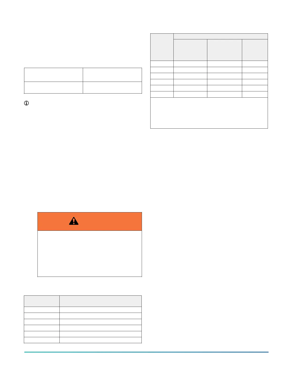
Table 8: Free area
Minimum free area required for each openingBtu/h
input
rating
Horizontal duct
(2,000 Btu/h)
Vertical duct
or opening to
outside
(4,000 Btu/h)
Round duct
(4,000 Btu/h)
40,000
20 in.
2
(129 cm
2
) 10 in.
2
(64 cm
2
)
4 in. (10 cm)
60,000
30 in.
2
(193 cm
2
) 15 in.
2
(97 cm
2
)
5 in. (13 cm)
80,000
40 in.
2
(258 cm
2
) 20 in.
2
(129 cm
2
)
5 in. (13 cm)
100,000
50 in.
2
(322 cm
2
) 25 in.
2
(161 cm
2
)
6 in. (15 cm)
120,000
60 in.
2
(387 cm
2
) 30 in.
2
(193 cm
2
)
7 in. (18 cm)
130,000
65 in.
2
(419 cm
2
) 33 in.
2
(213 cm
2
)
7 in. (18 cm)
Example: Determining free area.
Appliance 1 Appliance 2 Total input
100,000 + 30,000 = (130,000 ÷ 4,000) = 32.5 in.
2
vertical
Appliance 1 Appliance 2 Total input
100,000 + 30,000 = (130,000 ÷ 2,000) = 65 in.
2
horizontal
Air supply openings and ducts
• An opening may be used in lieu of a duct to provide
to provide the outside air supply to an appliance
unless otherwise permitted by the authority having
jurisdiction. The opening must be located within 12
in. (30.5 cm) horizontally from the burner level of the
appliance. See Combustion air source from outdoors
and for additional information and the safety check
procedure.
• The duct must be either metal or a material meeting
the class 1 requirements of CAN4-S110 Standard for
Air Ducts.
• The duct must be at least the same cross-sectional
area as the free area of the air supply inlet opening to
which it connects.
• The duct must terminate within 12 in. (30.5 cm) above
and within 24 in. (61 cm) horizontally from the burner
level of the appliance having the largest input.
• Only use a square or rectangular-shaped duct when
the required free area of the supply opening is 9
in
2
(58.06 cm
2
) or larger. When using a square or
rectangular duct, its small dimension must not be less
than 3 in. (7.6 cm).
• An air inlet supply from outdoors must be equipped
with a means to prevent the direct entry of rain and
wind that does not reduce the required free area of
the air supply opening.
• Locate an air supply inlet opening from the outdoors
not less than 12 in. (30.5 cm) above the outside grade
level.
Installation Manual: RL18 Single-Stage Standard ECM Residential Gas Furnaces (Non-condensing Multi-position Standard
Low NOx)
25
Johnson Controls Ducted Systems