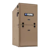
Figure 25: Combustion airflow path through the
furnace casing to the burner compartment
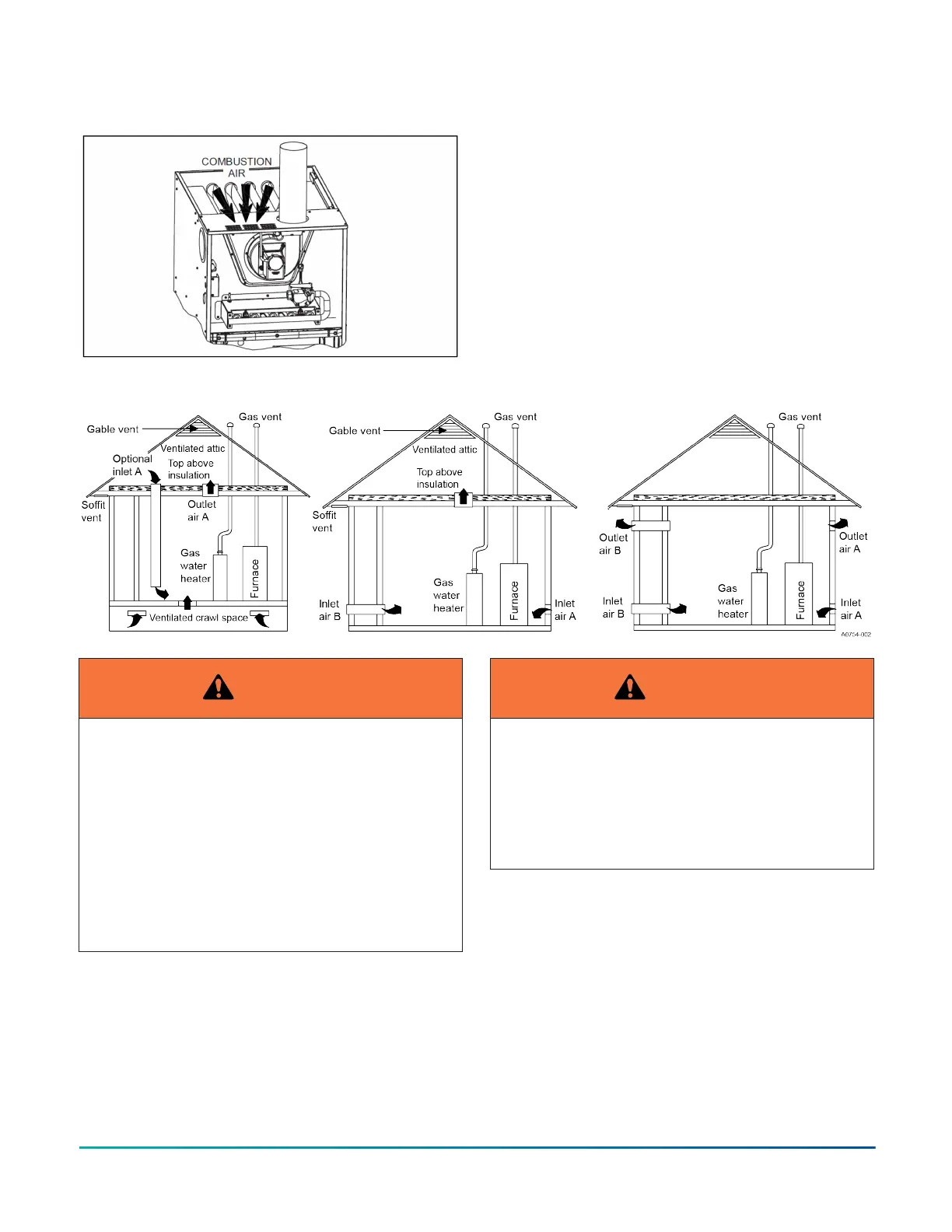
Figure 26: Combustion airflow path through the furnace casing to the burner compartment
WARNING
This type of installation requires that the supply
air to the appliance(s) be of a sufficient amount to
support all of the appliance(s) in the area. Operation
of a mechanical exhaust, such as an exhaust fan,
kitchen ventilation system, clothes dryer or fireplace
may create conditions requiring special attention to
avoid unsatisfactory operation of gas appliances. A
venting problem or a lack of supply air will result in a
hazardous condition, which can cause the appliance
to soot and generate dangerous levels of CARBON
MONOXIDE, which can lead to serious injury, property
damage and / or death.
WARNING
Examine the heat exchanger, vent pipe, combustion
air passages, vent connectors, and chimney to be
sure they are clear and free of obstructions.
Note: Proper orientation on the heat exchanger is
for the compressed heat transfer blade portion to be
up and away from the burner section, towards the air
leaving end of the furnace.
An unconfined space is not less than 50 ft
3
(1.42 m
3
)
per 1,000 Btu/h (0.2928 kW) input rating for all of the
appliances installed in that area.
Rooms communicating directly with the space containing
the appliances are considered part of the unconfined
space, if doors are furnished with openings or louvers.
A confined space is an area with less than 50 ft
3
(1.42
m
3
) per 1,000 Btu/h (0.2928 kW) input rating for all of
the appliances installed in that area. The following must
be considered to obtain proper air for combustion and
ventilation in confined spaces.
Installation Manual: RL18 Single-Stage Standard ECM Residential Gas Furnaces (Non-condensing Multi-position Standard
Low NOx)
24
Johnson Controls Ducted Systems