25
RW SERIES REVERSIBLE CHILLER INSTALLATION MANUAL
Inputs and Outputs Confi guration
DUAL STAGE WW
Input Name Input Output Name Output
Entering Load Water Temperature AI 1 Compressor 1 DO1
Leaving Load Water Temperature 1 AI 2 Compressor 2 DO2
Source Heating Freeze Detection 1 AI 3 Reversing Valve DO3
Source Heating Freeze Detection 2 AI 4 Accessory DO4
Load Cooling Freeze Detection 1 AI 5 Compressor 1 Alarm DO5
Load Cooling Freeze Detection 2 AI 6 Compressor 2 Alarm DO6
Network Output DO7
Load Flow Proving Switch DI 1 Network Output DO8
Emergency Shutdown DI 2 Network Output D09
Stage 2 Low Pressure DI 3
Source Htg Freeze Detection Select - 30ºF DI 4 Future PWM1
Load Htg Freeze Detection Select - 30ºF DI 5 Future PWM2
Stage 1 Low Pressure DI 6
Thermostat Y1 DI 7
Thermostat Y2 DI 8
Thermostat B DI 9
Source Flow Proving Switch D10
Stage 1 High Pressure DI11
Stage 2 High Pressure DI12
XP10 Expansion Card
Input Name Input Output Name Output
Entering Source Water Temperature AI 1 Unused DO 1
Leaving Source Water Temperature 1 AI 2 Unused DO 2
Current Switch 1 - Compressor 1 AI 3 Unused DO 3
Current Switch 2 - Compressor 2 AI 4 Unused DO 4
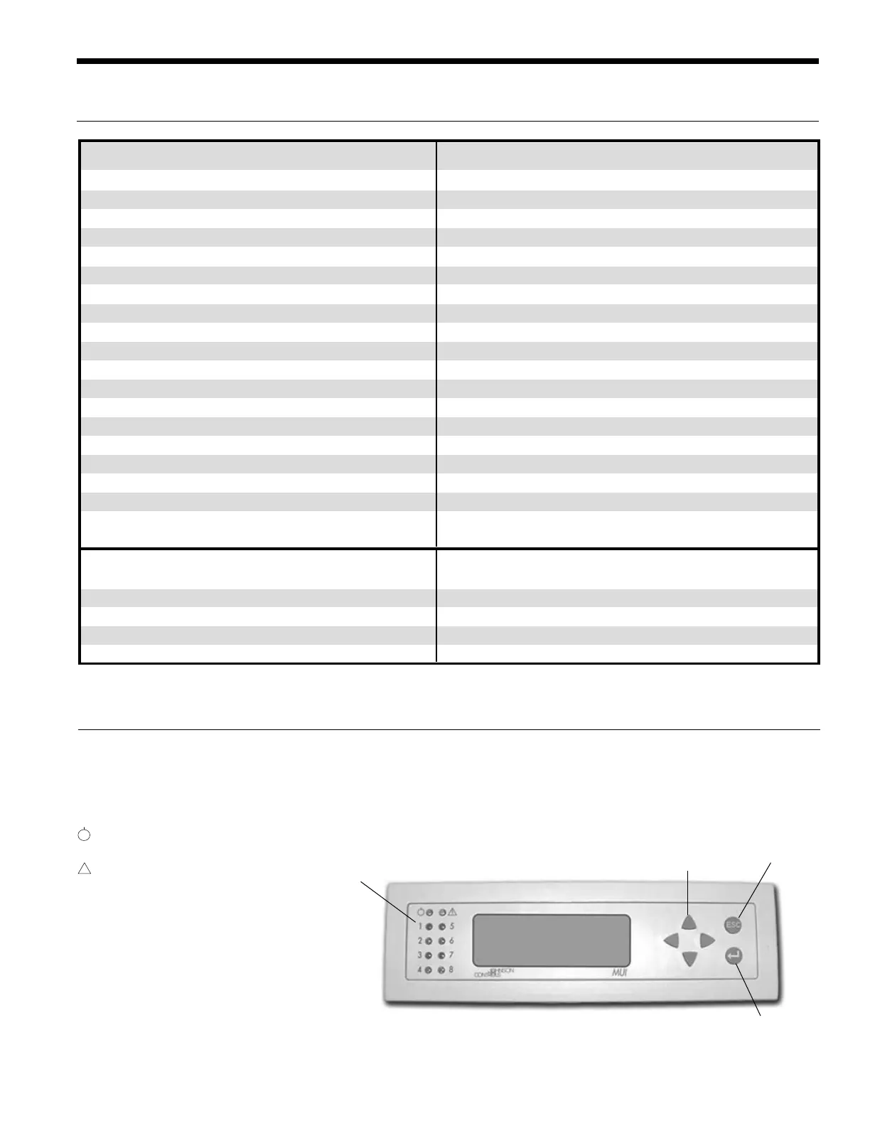
Unit Display and Interface
The Unit Display allows the user to view entering and leaving water temperatures, freeze detection readings, inputs and outputs, and
allows the user enable and disable certain control functions through the various menus. The interface also displays all faults on the LCD
once the unit has locked out to aid in diagnostics.
There are 10 LED indicator lights that indicate the following:
Power - Shows that the FX processor is
operational
Alarm - Lights when there is a
lock-out or faulty freeze
detection sensor
1 - Flashing shows Compressor 1
is running
2 - Flashing shows Compressor 2
is running
3 - On shows Compressor 2 is lead
4 - On shows Reversing valve in cool
8 - On shows unit in ‘Test’ mode
Figure 5 - Unit Display/Interface
Escape Key
Return Key
Directional Keys
LEDs
!

 Loading...


