31
RW SERIES REVERSIBLE CHILLER INSTALLATION MANUAL
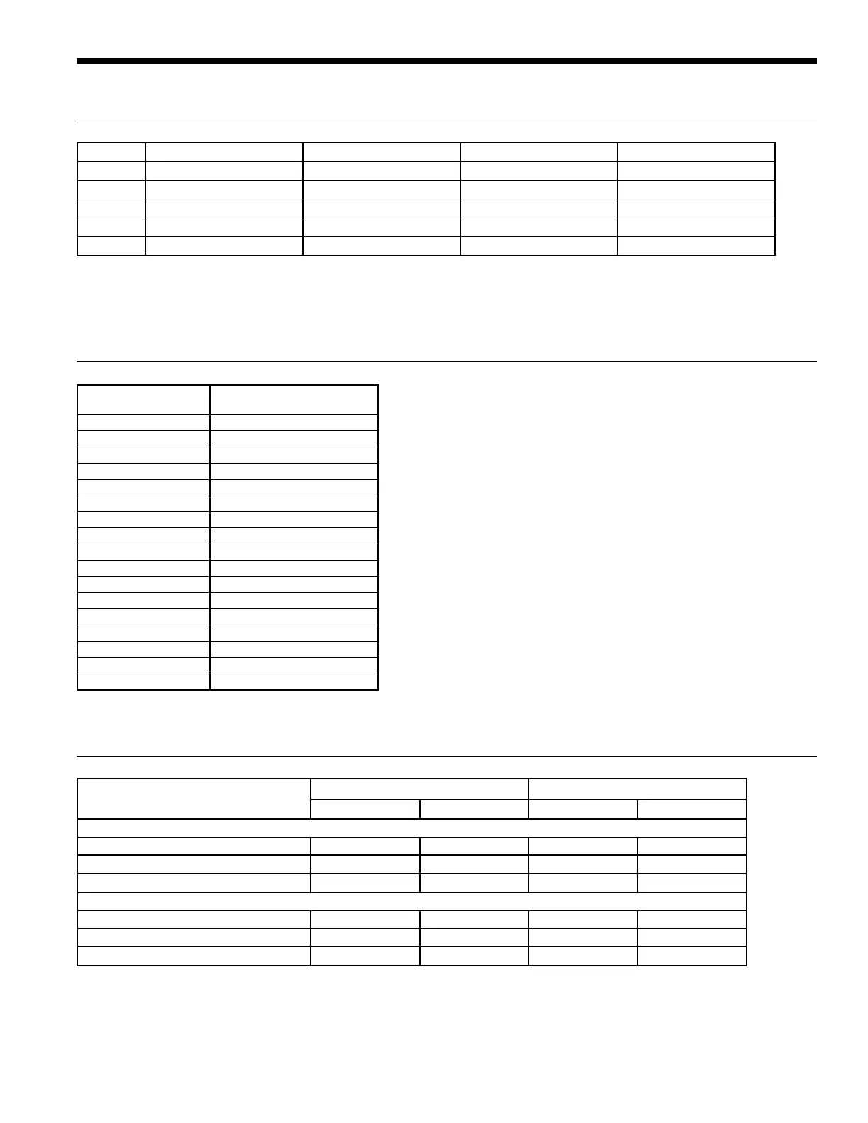
Compressor Resistance
Model 208-230 380 460 575
120 .539 / .528 /.528 .575 / .575 / .575 2.116 / 2.088 / 2.072 3.333 / 3.289 / 3.263
180 .32 / .32 / .33 N/A 1.29 / 1.28 / 1.33 1.99 / 1.96 / 2.05
240 .33 / .33 / .33 N/A 1.13 / 1.11 / 1.10 1.73 / 1.66 / 1.75
360 .20 / .20 / .20 0.57 / 0.57 / 0.57 .83 / .83 / .83 1.32 / 1.32 / 1.32
600 N/A .36 / .36 / .36 0.52 / .52 / .52 .82 / .82 / .82
1/30/14
Resistance values listed in ohms and measured at 25C between phases 1-2, 1-3, 2-3, respectively.
Specialized measurement device should be used for accurate resistance readings due to low resistance values.
Thermistor Resistance
Thermistor
Temperature (°F)
FX10
Resistance (Ohms)
5 746-770
14 775-803
23 808-836
32 841-869
41 875-903
50 910-938
59 946-974
68 981-1013
77 1019-1051
86 1058-1090
95 1097-1
129
104 1137-1169
113 1179-1211
122 1221-1253
131 1261-1297
140 1305-1341
149 1350-1386
1/30/14
Operating Limits
Operating Limits
Cooling Heating
(°F) (°C) (°F) (°C)
Source Side Water Limits
Min. Entering Water 30 -1.1 30 -1.1
Normal Entering Water 85 29.4 60 15.6
Max. Entering Water 110 43.3 90 32.2
Load Side Water Limits
Min. Entering Water 50 10.0 60 15.6
Normal Entering Water 60 15.6 100 37.8
Max. Entering Water 90 32.2 120 48.9
Notes:
Minimum/maximum limits are only for start-up conditions, and are meant for bringing the space up to occupancy temperature. Units are not designed
to operate at the minimum/maximum conditions on a regular basis. The operating limits are dependant upon three primary factors: 1) entering source
temperature, 2) entering load temperature, and 3) flow rate (gpm). When any of the factors are at the minimum or maximum levels, the other two
factors must be at the normal level for proper and reliable unit operation. Consult the Capacity Tables for each model to determine allowable normal
operating conditions. Units are not designed for outdoor installation.

 Loading...


