542933-UIM-D-0513
Johnson Controls Unitary Products 39
Exiting Service Mode
SERVICE TOOL SETUP
The service tool application is defined as a Touch Screen Communicating Control that is being used
to trouble shoot/view details of a system. The Touch Screen Communicating Control can access the
system from the indoor and the outdoor controls via the communication ports outlined earlier in this
document.
To set up the service tool for operation:
1. Extend wire harness.
Extending the Communication Harness
Each Touch Screen Communicating Control is supplied with a communicating plug harness. This
harness is 18” long and can be extended with thermostat wire to allow more convenient and safe
use of the service tool.
To extend the harness:
a. Use 5-6 feet of thermostat wire (enough to maintain a safe/comfortable distance from
the high voltage in the control panels) and 4 wire nuts.
b. Use the wire nuts to connect the stripped ends of the communicating plug harness to
the loose/stripped ends of the thermostat wire.
c. Wire the non-plug end of the extended harness to the terminal block of the mounting
back plate of the Touch Screen Communicating Control.
d. Snap the Touch Screen Communicating Control on the back plate.
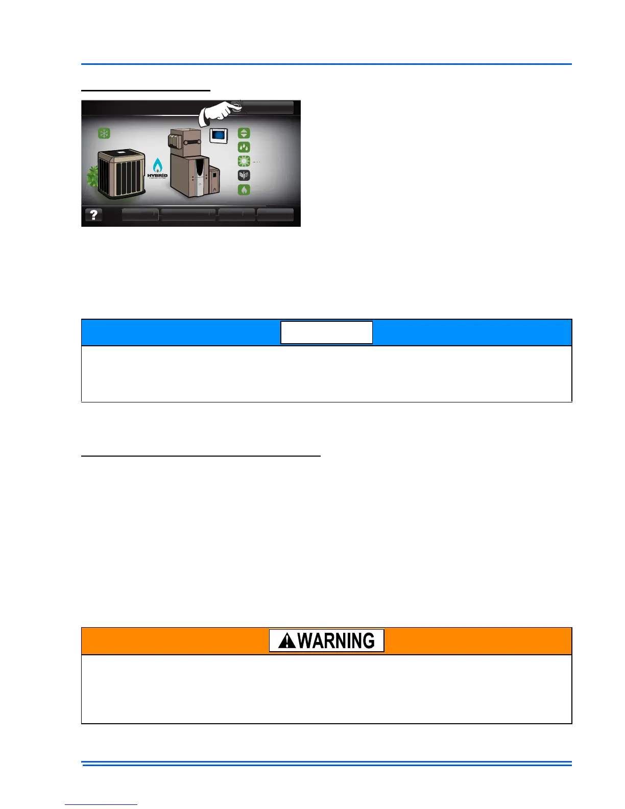
To exit service mode, press the button in the
upper, right hand corner of the system map
screen. When the exit button is pressed, the
Touch Screen Communicating Control will re-val-
idate and return to normal operation.
While the service tool is highly useful device mode, the Touch Screen Communicating Control
that has been configured as the “master” of the communicating system contains all the informa-
tion available for trouble shooting purposes while the service tool function may have some limita-
tions.
ELECTRICAL OPERATION HAZARD
Failure to follow this warning could result in personal injury, death, or equipment damage.
Before installing, modifying, or servicing system, the main electrical disconnect switch must be in
the OFF position. There may be more than 1 disconnect switch. Lock out and tag switch with a
suitable warning label.

 Loading...