542933-UIM-D-0513
Johnson Controls Unitary Products 5
5. Remove mounting back plate.
6. Drill holes (3/16” in diameter) in the marked area to accommodate the anchors (provided in the
kit).
7. Place anchors in the pre-drilled holes. Be sure that the anchors are fully inserted.
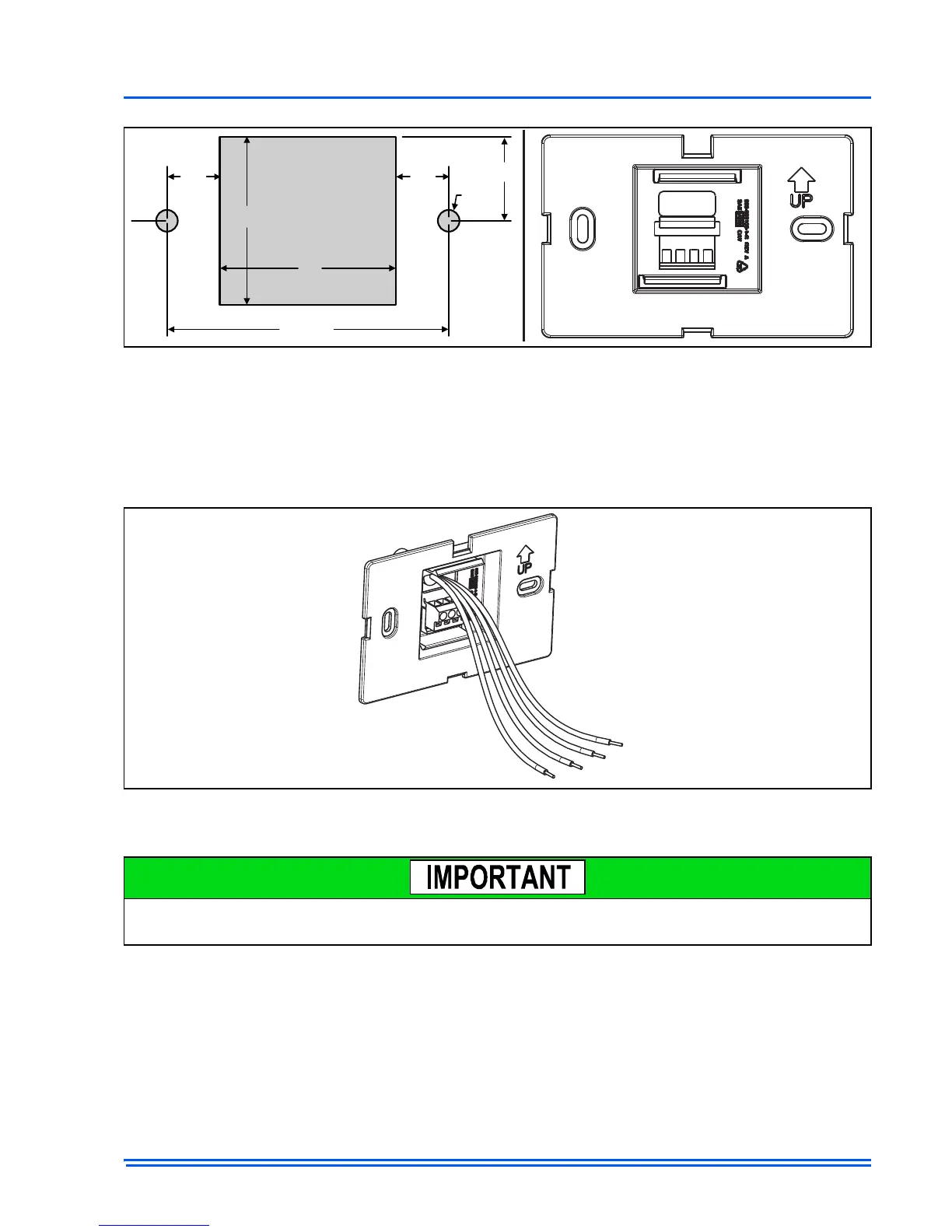
8. Pull low voltage wires through the mounting back plate as shown in Figure 3.
9. Connect low voltage wires as instructed in the wiring section of this document.
10.Screw the wired mounting back plate to the wall using the screws provided in the kit.
11. Align the terminal screw block with the pins on the back of the Touch Screen Communicating
Control and snap it to the mounting back plate.
REMOVING CONTROL MOUNTING BACK PLATE
Gently remove by tilting up to release the bottom of the Touch Screen Communicating Control and
then pull out/down to completely remove.
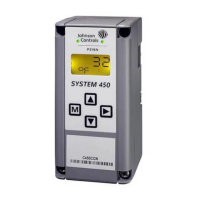
FIGURE 2:
Mounting Back Plate Dimensions
FIGURE 3: Wires Pulled Through Mounting Back Plate
Fastening the wires in the terminal block before attaching the back plate to the wall will ultimately
ease the installation of the wire. Once on the wall, the terminal block has limited accessibility.

 Loading...