Hardware Installation S300-DIN-RDR2S Module
20 24-10239-413 Rev. A
This document contains confidential and proprietary information of Johnson Controls, Inc.
© 2010 Johnson Controls, Inc.
Grounding Cable Shields
This section gives instructions for grounding cable shields at data and low voltage
installations. Follow these guidelines for electromagnetic compatibility (EMC)
conformity and to improve system reliability.
The following key points will help ensure a good ground for cable shields:
Shield must be connected to chassis ground.
Grounding points should be free from paint and corrosion.
Keep the cable’s shield as short as possible. Ideally, the length of exposed
shield should not exceed 3 inches (76 mm). This length includes any
crimp-type terminal lug used to connect the shield to chassis ground.
Do not connect the cable shield to any existing internal ground (earth)
bonding straps.
The following information will help you decide
h
ow best to terminate the shield.
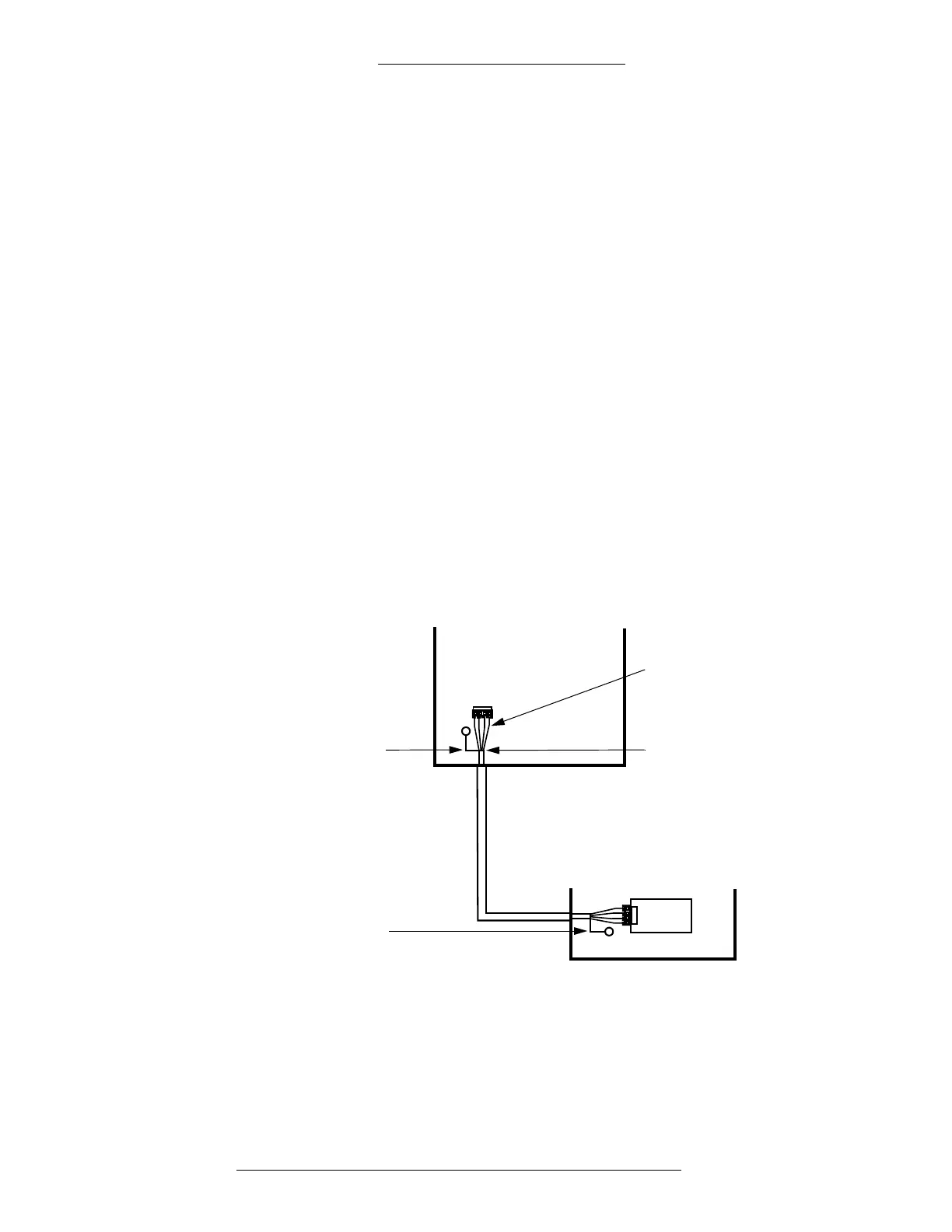
The equipment to be interconnected is at the same
ground voltage potential
(zero volts).
This scenario is typically used when the units are in close proximity to each other.
Connect the cable’s shield
at both ends of the cable to the closest chassis ground
point.
Separated wires of
cable are not shielded
The screen-type shield is
inside the enclosure, no
more than 2 inches (5 cm)
Short wire is
connected
from shield to
enclosure of
unit 1
Short wire is
connected
from shield to
enclosure of
unit 2
UNIT2
UNIT1
PCBA

 Loading...


