79
Installation Instructions
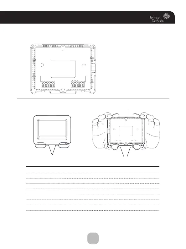
The T9500 Thermostat Backplate
W3 3rd stage heat circuit /2nd stage aux heat/humidification/dehumidification
W2 2nd stage heat circuit/1st stage aux heat
W1/O/B 1st stage heat circuit/reversing valve
Y2 2nd stage compressor relay
Y1 1st stage compressor relay
G fan relay
R 24 VAC return
C 24 VAC common
SENSOR remote/outdoor/supply/return sensor connections
IMPORTANT: This thermostat requires both R (24 VAC Return) and
C (24 VAC Common) be connected to the backplate terminals.
To remove the thermostat backplate:
Using the Finger Pull Areas, pull the
front housing away from the backplate.
Look for these tabs to locate
the pull areas
Pull out with thumbs in these areas
Backplate
Front Housing
NOTE:
The backplate does not fully
cover a full size vertical junction
box. The ACC-WALLPLT
touch screen wallplate or
a single-gang, horizontally
mounted junction box would
be needed for that type of
installation.
W3/AUX
W2
W1/O/B
Y2
Y1
SENSOR