JOHNSON CONTROLS
12
FORM 130.13-NOM8 (1021)
MODEL TCSC SIZES 07-23 WITH ELECTRIC HEAT
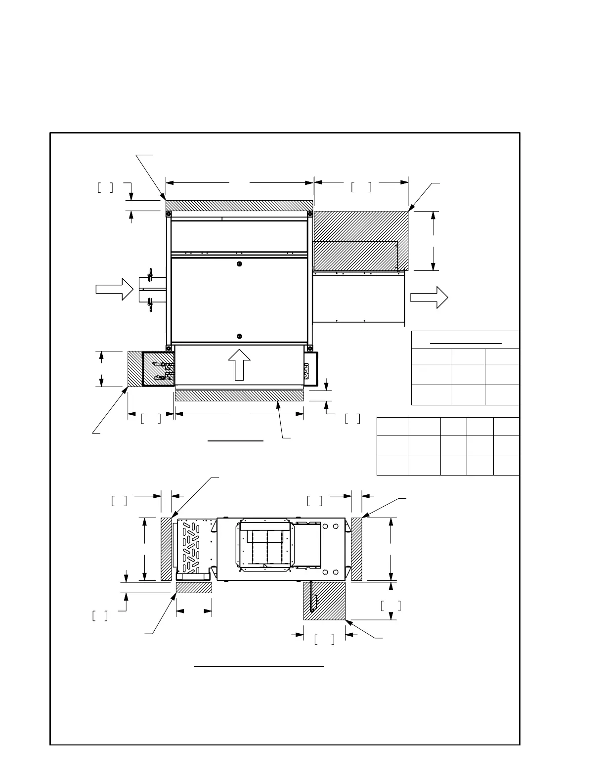
Service And Clearance Requirements
Drawings not for installation purposes. Refer to unit and size-specic
submittal drawings for installation.
11"
279
2-1/2"
64
"C"
22-1/2"
572
"A"
"B"
2-1/2"
64
"F"
FLOW
PRIMARY
AIR
FLOW
AIR
ADDITIONAL ELECTRICAL
ENCLOSURE SIDE ACCESS
OPTIONAL
VALVE PACKAGE
ACCESS
ELECTRIC HEAT
SIDE ACCESS
INDUCED
AIR
FLOW
TOP VIEW
OPTIONAL FILTER
REMOVAL
SIDE ACCESS
2-1/2"
64
"A"
"E"
2-1/2"
64
9"
229
10"
254
"D"
2-1/2"
64
DRIP TRAY
REMOVAL
BOTTOM ACCESS
ADDITIONAL
ELECTRICAL
ENCLOSURE
SIDE ACCESS
ELECTRICAL ENCLOSURE
BOTTOM ACCESS
DOOR (OPEN POSITION)
DISCHARGE END VIEW
OPTIONAL FILTER
REMOVAL
SIDE ACCESS
NOTES:
1. All dimensions in Inches [millimeters]. All dimensions
±
1/4" [6mm].
2. Left Hand unit shown, Right Hand unit opposite.
3. Standard Electrical Enclosure is integrated into unit side. Includes (4) knockouts on (2) sides. Provide
sufficient clearance to access electrical controls and comply with applicable codes and ordinances.
4. NEC clearance can be from the bottom or side of the unit. When using side access, 9” of bottom
clearance recommended to access optional electrical disconnect and EC motor control.
UNIT
SIZE
"C"
"D"
"E"
"F"
07&10
35-1/2"
[902]
15"
[381]
15"
[381]
14"
[356]
15,
20,23
40-1/2"
[1029]
18"
[457]
18"
[457]
17"
[432]
COOLING COIL
# ROWS
"A"
"B"
2 - 4
8-1/2"
[216]
31"
[787]
6 - 8
13"
[330]
36"
[914]
PAGE 1 OF 1
10-80119-J
A
5/28/21
DIMENSIONS ARE IN INCH [MM] FORMAT
+/- 1/8 [3] UNLESS OTHERWISE NOTED
DRAWING NO
TITLE:
REV
SHEET
DATE
ALL DRAWINGS ARE SUBJECT TO CHANGE
WITHOUT PRIOR NOTICE
DO NOT SCALE DRAWING
SUBMITTAL DRAWING
THIS DRAWING CONTAINS PROPRIETARY DATA. UNAUTHORIZED DISCLOSURE,
REPRODUCTION, OR USE IS STRICTLY PROHIBITED WITHOUT WRITTEN PERMISSION.
UNCONTROLLED WHEN PRINTED
MODEL TCSC SIZES 07-23, ELECTRIC HEAT,
EXTERNAL SPACE REQUIREMENTS
 Loading...