5594752-UIM-C-1119
Johnson Controls Ducted Systems 13
SECTION VI: TWINNING AND STAGING
In applications where more heating capacity or more airflow capacity is
needed than what one furnace can deliver, twinning can be used to
make two furnaces operate in tandem (as long as the two furnaces
have the same model number). When two identical furnaces are
installed using the same duct system, it is very important that the two
furnace circulating air blowers operate simultaneously at all times. If
one blower starts before the second blower, the duct system will
become pressurized and the blower on the second furnace may turn
backwards causing the second furnace to overheat, resulting in dam-
age to the furnace. Twinning is used to make two furnaces operate in
tandem, using one duct system, one room thermostat and causing both
furnaces blowers to turn on and off simultaneously.
TWINNING DUCT SYSTEM
Twinned furnaces must only be applied on a common duct system. A
single air supply plenum must be used for both furnaces and indoor
coil(s). Separate plenums and supply ducts systems cannot be utilized.
A single return air plenum, common to both furnaces must be used. It is
suggested that a return platform be utilized, with bottom air entrance
into each furnace. If a side entrance return system is used, the common
return duct must be divided equally so as to supply each furnace with
an equal amount of return air.
Both furnaces must be identical models in both heating capacity and
CFM capacity. Both furnaces must be operated on the same motor
speed taps. Detailed and specific indoor blower motor wiring and con-
trol wiring information can be found in Source 1 twinning kit S1-
33103764000 installation instructions. See typical application, Figure
14.
If furnace staging is desired with two single stage furnaces on a com-
mon duct, where the gas burner on the first furnace operates on W1
and the gas burner on the second furnace operates on W2, then the
use of an air-mixing device in the plenum to mix the air from both fur-
naces is strongly recommended. The mixing device must be installed
before any ducts that supply air to occupied spaces. Twinning causes
both indoor fans to operate simultaneously. If a mixing device is not
used, any ducts that are connected down stream from the furnace that
is not operating in heat mode will be supplying cold air to the occupied
spaces.
SECTION VII: VENT SYSTEM
VENT CONNECTIONS
All models are provided with a flue transition that is sized for 4” diame-
ter vent connections. If a larger size vent connector is required, that
connection must be installed external to the furnace. Figure 15 shows
the furnace as it is shipped from the factory. To convert to a horizontal
or downflow position, remove the four screws that secure the inducer
assembly and rotate 90º being careful not to damage the gasket. Rein-
stall screws. Remove cap from appropriate vent outlet location on the
cabinet, cut insulation in cabinet to same size as the hole provided and
reinstall cap in the hole in the top panel.
CATEGORY 1 - 450 F. MAX. VENT TEMP.
The venting system must be installed in accordance with Section 5.3,
Air for Combustion and Ventilation, of the National Fuel Gas Code
Z223.1/NFPA 54 (latest edition), or Sections 7.2, 7.3 or 7.4 of CSA
B149.1, National Gas and Propane Codes (latest edition) or applicable
provisions of the local building code and these instructions.
The furnace shall be connected to any type of B, BW or L vent connec-
tor, and shall be connected to a factory-built or masonry chimney. The
furnace shall not be connected to a chimney flue serving a sepa-
rate appliance designed to burn solid fuel.
It is recommended that the appliance is installed in a location where the
space temperature is 32ºF (0ºC) or higher. If the appliance is installed in
a location where the ambient temperature is below 32ºF (0ºC), the com-
bustion byproducts could condense causing damage to the appliance
heat exchanger.
This appliance may be common vented with another gas appliance for
residential installations as allowed by the codes and standards listed in
these instructions.
Non-HUD approved Modular Homes must be vented with an approved
roof jack and may not be common vented with other appliances.
VENTING
Category I venting consists of vertically venting one or more appliances
in B-vent or masonry chimney (as allowed), using single wall metal pipe
or B-vent connectors. Type B-vent system extends in a general vertical
direction and does not contain offsets exceeding 45º. A vent system
having not more than one 60º offset is permitted.
NOTICE
For twinning applications, Source 1 twinning kit S1-33103764000
MUST be used.
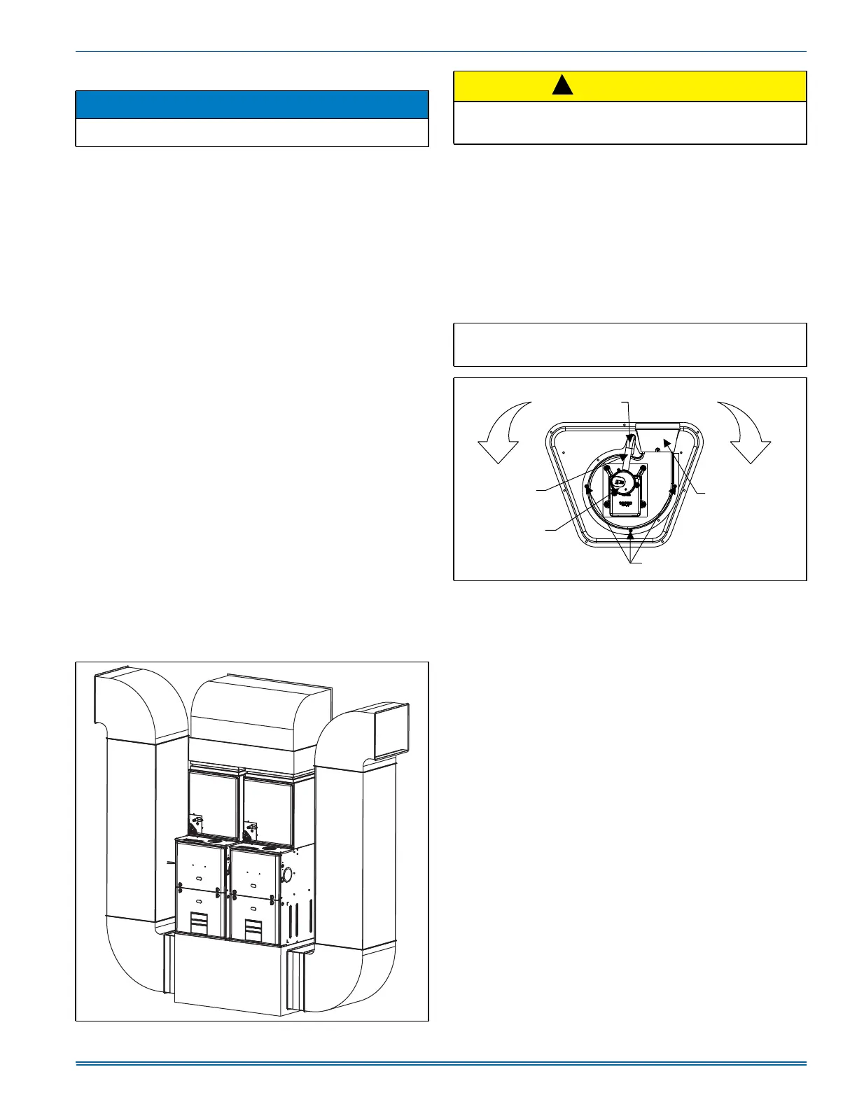
FIGURE 14: Twinned Furnaces
$
CAUTION
If a return duct is connected to only one furnace (with a connection
between the two furnaces) an imbalance in the airflow will occur and
the furnace furthest from the return plenum will overheat.
IMPORTANT: In downflow applications, do not block the combustion
air inlet. The furnace must be installed on a coil cabinet or subbase to
allow combustion air to enter the burner compartment.
FIGURE 15: Combustion Air Inducer
!
COMBUSTION AIR INDUCER
90° 90°
Mounting Screw
(Remove)
Flue Transition
(Do Not Remove)
Mounting Screw
(Remove)
Pressure
Switch
Pressure Switch
Tube Routing