5594752-UIM-C-1119
12 Johnson Controls Ducted Systems
ACCESSORY CONNECTIONS
The furnace control will allow power-switching control of various acces-
sories.
ELECTRONIC AIR CLEANER CONNECTION
Two 1/4” (6.4 mm) spade terminals (EAC and NEUTRAL) for electronic
air cleaner connections are located on the control board. The terminals
provide 115VAC (1.0 Amp maximum) during circulating blower opera-
tion.
HUMIDIFIER CONNECTION
Two 1/4” (6.4 mm) spade terminals (HUM and NEUTRAL) for humidifier
connections are located on the control board. The terminals provide
115VAC (1.0 Amp maximum) during heating system operation.
A mounting hole is provided on the control panel next to the furnace
control board for mounting a humidifier transformer if required.
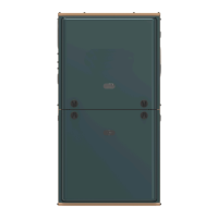
FIGURE 12: Thermostat Chart - Single Stage AC with Single Stage Furnaces
6LQJOH6WDJH$LU&RQGLWLRQHU±6LQJOH6WDJH)XUQDFH
<
)LUVW6WDJH
&RPSUHVVRU
:
6HFRQG6WDJH+HDW
*
)DQ
RU2
5HYHUVLQJ9DOYH
5
±9ROW+RW
:
)LUVW6WDJH+HDW
&
±9ROW&RPPRQ
&
±9ROW&RPPRQ
5
±9ROW+RW
<
6HFRQG6WDJH
&RPSUHVVRU
<<
)XOO6WDJH&RPSUHVVRU
*
)DQ
6,1*/(67$*(
(&0)XUQDFH
6,1*/(67$*(
$,5
&21',7,21(5
&
±9ROW&RPPRQ
5
±9ROW+RW
<
&RPSUHVVRU&RQWDFWRU
:
)XOO6WDJH+HDW
<
)LUVW
6WDJH&RPSUHVVRU
7+(50267$7
$
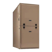
FIGURE 13: Thermostat Chart - Single Stage HP with Single Stage Furnaces
$
6LQJOH6WDJH+HDW3XPS±6LQJOH6WDJH)XUQDFH
:
6HFRQG6WDJH+HDW
*
)DQ
5
±9ROW+RW
:
)LUVW6WDJH+HDW
&
±9ROW&RPPRQ
&
±9ROW&RPPRQ
5
±9ROW+RW
<
6HFRQG6WDJH
&RPSUHVVRU
<<
)XOO6WDJH&RPSUHVVRU
*
)DQ
6,1*/(67$*(
(&0)XUQDFH
6,1*/(67$*(
+($73803
&
±9ROW&RPPRQ
5
±9ROW+RW
<
)LUVW6WDJH
&RPSUHVVRU
:
$X[LOLDU\+HDW
7+(50267$7
<
)LUVW6WDJH
&RPSUHVVRU
2
5HYHUVLQJ9DOYH
(QHUJL]HGLQ&RRO
RU2
5HYHUVLQJ9DOYH
<
)LUVW
6WDJH&RPSUHVVRU
:2XW
::
)LUVW6WDJH+HDW
1RWH5RRPWKHUPRVWDW0867
FRQWUROIRVVLOIXHORSHUDWLRQ