5594752-UIM-C-1119
22 Johnson Controls Ducted Systems
NOTES:
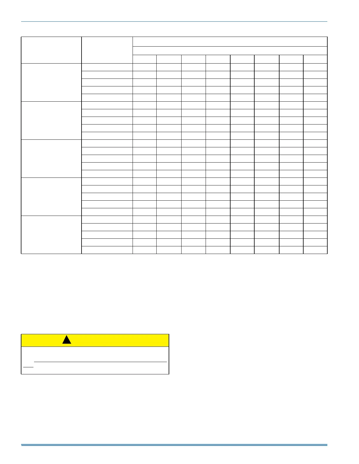
1. Airflow expressed in standard cubic feet per minute (SCFM).
2. Motor voltage at 115 V.
3. Not all speeds are recommended for use as heating speeds.
SECTION IX: SAFETY CONTROLS
CONTROL CIRCUIT FUSE
A 3-amp fuse is provided on the control circuit board to protect the 24-
volt transformer from overload caused by control circuit wiring errors.
This is an ATO 3, automotive type fuse and is located on the control
board.
BLOWER DOOR SAFETY SWITCH
This unit is equipped with an electrical interlock switch mounted in the
burner compartment. This switch interrupts all power at the unit when
the panel covering the blower compartment is removed.
Electrical supply to this unit is dependent upon the panel that covers the
blower compartment being in place and properly positioned.
ROLLOUT SWITCH CONTROLS
These controls are mounted on the burner assembly. If the temperature
in the area surrounding the burner exceeds its set point, the gas valve
is de-energized. The operation of this control indicates a malfunction in
the combustion air blower, heat exchanger or a blocked vent pipe con-
nection. Corrective action is required. These are manual reset controls
that must be reset before operation can continue.
PRESSURE SWITCHES
This furnace is supplied with a pressure switch, which monitors the flow
through the combustion air/vent piping system. This switch de-ener-
gizes the gas valve if any of the following conditions are present.
1. Blockage of vent piping or terminal.
2. Failure of combustion air blower motor.
LIMIT CONTROLS
There is a high temperature limit control located on the furnace vesti-
bule panel near the gas valve. This is an automatic reset control that
provides over temperature protection due to reduced airflow. This may
be caused by:
1. A dirty filter.
2. If the indoor fan motor should fail.
3. Too many supply or return registers closed or blocked off.
The control module will lockout if the limit trips 5 consecutive times. If
this occurs, control will reset & try ignition again after 1 hour.
100C16
High 1795 1755 1715 1673 1631 1587 1533 1479
Medium High 1464 1417 1364 1325 1290 1227 1188 1138
Medium 1217 1171 1120 1072 1021 978 924 869
Medium Low 1062 1011 956 910 858 801 738 669
Low 905 847 784 732 668 601 540 465
100C20
High 2219 2179 2136 2095 2044 2001 1952 1912
Medium High 1994 1951 1911 1872 1820 1774 1733 1678
Medium 1727 1687 1648 1595 1558 1502 1456 1406
Medium Low 1618 1574 1528 1480 1432 1383 1337 1288
Low 1410 1364 1316 1255 1206 1164 1109 1042
120C16
High 1765 1721 1684 1635 1606 1542 1503 1442
Medium High 1429 1384 1340 1292 1256 1209 1164 1114
Medium 1207 1169 1119 1077 1028 977 930 888
Medium Low 1055 1018 955 907 862 810 761 705
Low 885 834 783 733 675 618 544 500
120C20
High 2235 2199 2148 2108 2066 2034 1984 1932
Medium High 1960 1901 1860 1819 1776 1723 1682 1642
Medium 1693 1640 1593 1557 1504 1455 1413 1365
Medium Low 1580 1533 1488 1444 1394 1342 1296 1244
Low 1417 1362 1313 1269 1223 1169 1120 1079
130D20
High 2229 2182 2133 2088 2047 1996 1946 1893
Medium High 2009 1968 1925 1881 1829 1778 1737 1679
Medium 1818 1765 1729 1675 1616 1580 1540 1480
Medium Low 1569 1520 1472 1427 1376 1329 1281 1237
Low 1448 1394 1341 1275 1221 1183 1131 1085
Table 13: Blower Performance CFM - Any Position (without filter) (Continued)
Models Speed
Airflow Data (SCFM)
1, 2
Ext. Static Pressure (in. H2O)
0.1 0.2 0.3 0.4 0.5 0.6 0.7 0.8
CAUTION
Main power to the unit must still be interrupted at the main power dis-
connect switch before any service or repair work is to be done to the
unit. Do not rely upon the interlock switch as a main power discon-
nect. Blower and burner must never be operated without the blower
panel in place.
!