5594752-UIM-C-1119
20 Johnson Controls Ducted Systems
AIRFLOW SETTINGS
Cooling Airflow Settings
This unit is equipped with a five-speed blower motor. The desired cool-
ing airflow may be selected by connecting the desired motor speed tap
wire to the HI COOL terminal on the control board. The speed should
be selected so as to deliver approximately 350-400 CFM per ton of A/C
cooling capacity. Use of airflow outside of this range may result in
diminished air conditioning performance and may result in lower overall
energy efficiency and higher electric utility bills. See Table 12 for default
cooling blower settings.
Continuous Fan Airflow Default Setting
The default blower speed for continuous fan operation is LOW speed.
The continuous fan speed is set at the factory to the default continuous
fan blower speed.
In certain circumstances, it may be necessary to move the continuous
fan speed to a different speed tap. However, doing so will result in
higher than normal electrical energy usage and higher than normal
electric utility bills.
Continuous Fan Jumpers
This furnace may be operated in continuous fan mode by setting the
wall thermostat FAN switch to ON. To select the desired continuous fan
airflow, place the FAN SPEED jumper on the control board on the pins
adjacent to the desired speed. There are four options:
1. With the FAN SPEED jumper in the “G” position, the blower will run
during continuous fan operation at the motor speed connected to
the “G” terminal on the control board.
2. With the FAN SPEED jumper in the “HI COOL” position, the blower
will run during continuous fan operation at the motor speed con-
nected to the “HI COOL” terminal on the control board.
3. With the FAN SPEED jumper in the “LO COOL” position, the blower
will run during continuous fan operation at the motor speed con-
nected to the “LO COOL” terminal on the control board.
4. With the FAN SPEED jumper in the “HEAT” position, the blower will
run during continuous fan operation at the motor speed connected
to the “HEAT” terminal on the control board.
The default position is with the jumper in the "G" position and the LOW
speed motor wire on the "G" terminal. In certain circumstances, it may
be necessary to move the continuous fan speed to a different speed
tap. However, doing so is not recommended because it will result in
higher than normal electrical energy usage and higher than normal
electric utility bills.
Gas Heating Airflow Default Setting
This unit is equipped with a five-speed blower motor. The heating
blower speed is set at the factory to the default blower speed, which is
the blower speed that will deliver the correct airflow for proper heating
operation in most applications. The default heating blower speed for
each model is shown in Table 12. Use of a heating speed other than the
default heating blower speed may result in reduced energy efficiency
and higher electric utility bills.
In certain circumstances, it may be necessary to move the heating
blower speed to a different motor speed tap.
Not all five motor speeds
are appropriate for gas heating operation. The use of heating airflow on
a speed other than the default speed will result in diminished heating
performance and may cause the furnace temperature limit controls to
shut down the furnace.
Measurement of Temperature Rise
After about 5 minutes of operation, determine the furnace temperature
rise. Measure the temperature of both the return air and the heated air
in the ducts, about six feet (1.83 m) from the furnace where they will not
be affected by radiant heat. Increase the blower speed to decrease the
temperature rise. Decrease the blower speed to increase the tempera-
ture rise.
The blower speed taps are located on the furnace control board in the
blower compartment. Refer to Figure 20 and the unit-wiring label to
change the blower speed. To use the same speed tap for heating and
cooling, the heat terminal and cool terminal must be connected using a
jumper wire and connected to the desired motor lead. Place all unused
motor leads on park terminals. Two park terminals are provided.
ADJUSTMENT OF FAN CONTROL SETTINGS
This furnace is equipped with a time-on/time-off heating fan control. The
fan on delay is fixed at 30 seconds. The fan off delay has 4 settings (60,
90, 120 and 180 seconds). The fan off delay is factory set to 120 sec-
onds. The fan-off setting must be long enough to adequately cool the
furnace, but not so long that cold air is blown into the heated space.
The fan-off timing may be adjusted by positioning the jumper on two of
the four pins as shown in Figure 20.
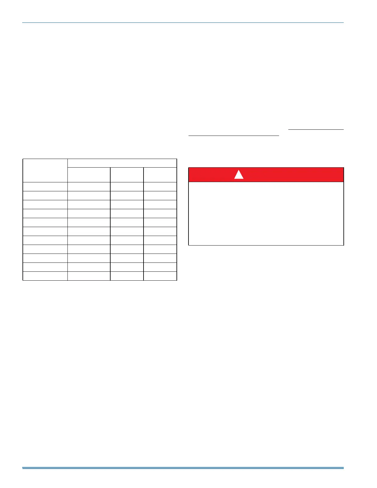
Table 12: Default Blower Speeds
Model Number
Default Blower Speeds
Heat Cool
Continuous
Fan
040A12 Medium Low (4) High (1) Low (5)
060A12 Medium Low (4) High (1) Low (5)
080B12 Medium (3) High (1) Low (5)
080C16 Medium (3) High (1) Low (5)
080C20 Low (5) High (1) Low (5)
100C12 Medium High (2) High (1) Low (5)
100C16 Medium (3) High (1) Low (5)
100C20 Medium Low (4) High (1) Low (5)
120C16 Medium High (2) High (1) Low (5)
120C20 Medium Low (4) High (1) Low (5)
130D20 Medium (3) High (1) Low (5)
DANGER
The temperature rise, or temperature difference between the return
air and the supply (heated) air from the furnace, must be within the
range shown on the furnace rating plate and within the application
limitations shown in SECTION V.
The supply air temperature cannot exceed the “Maximum Supply
Air Temperature” specified in these instructions and on the furnace
rating plate. Under NO circumstances can the furnace be allowed to
operate above the Maximum Supply Air Temperature. Operating the
furnace above the Maximum Supply Air Temperature will cause pre-
mature heat exchanger failure, high levels of Carbon Monoxide, a fire
hazard, personal injury, property damage, and/or death.
!