5594752-UIM-C-1119
Johnson Controls Ducted Systems 5
If a matching cased indoor coil is used, it may be placed directly on the
furnace outlet and sealed to prevent leakage. If an uncased indoor coil
with a thermoplastic drain pan is to be installed in the upflow/horizontal-
configuration, then extra 2” minimum spacing may be needed to ensure
against drain pan distortion.
On all installations without an indoor coil, a removable access panel is
recommended in the outlet duct such that smoke or reflected light
would be observable inside the casing to indicate the presence of leaks
in the heat exchanger. This access cover shall be attached in such a
manner as to prevent leaks.
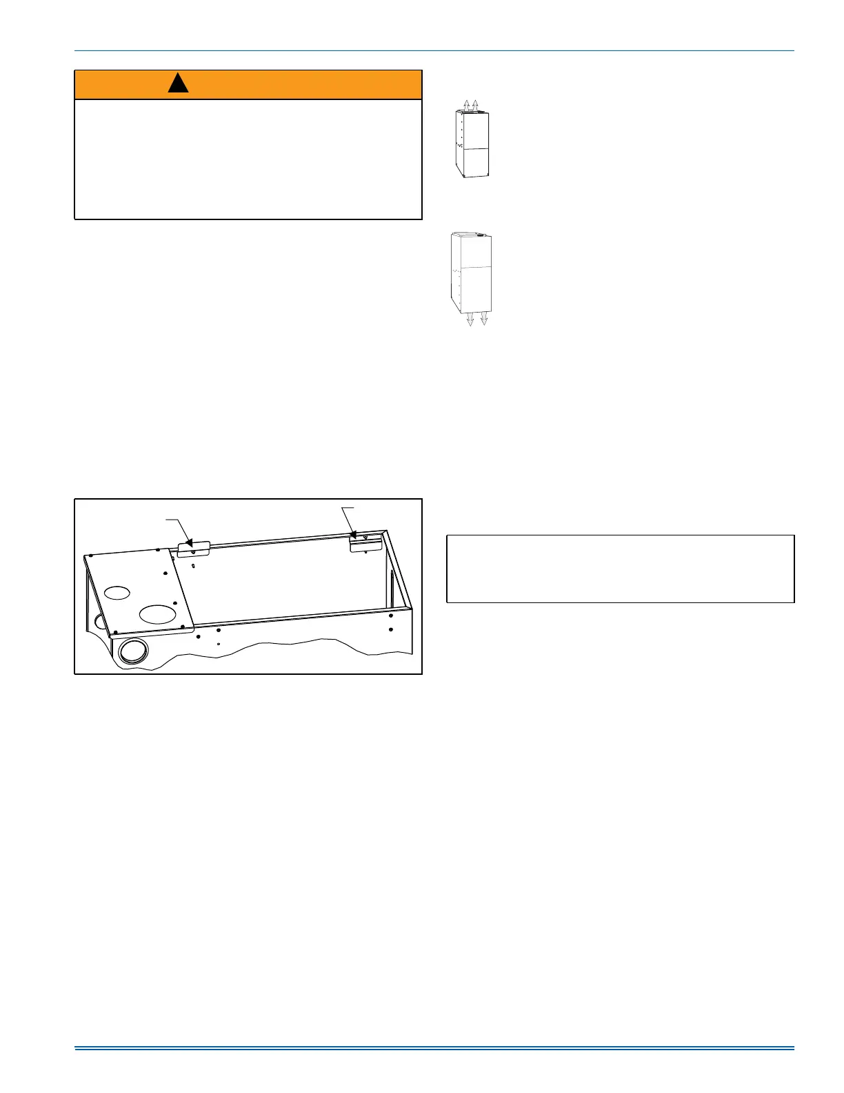
DUCT FLANGES
Four flanges are provided to attach ductwork to the furnace. These
flanges are rotated down for shipment. In order to use the flanges,
remove the screw holding an individual flange, rotate the flange so it is
in the upward position and reinstall the screw then repeat this for all 4
flanges.
If the flanges are not used, they must remain in the rotated down posi-
tion as shipped.
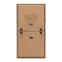
DUCTWORK INSTALLATION AND SUPPLY PLENUM
CONNECTION - UPFLOW/HORIZONTAL
Attach the supply plenum to the furnace outlet. The use of
an approved flexible duct connector is recommended on all
installations. This connection should be sealed to prevent
air leakage. The sheet metal should be crosshatched to
eliminate any popping of the sheet metal when the indoor
fan is energized.
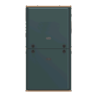
FLOOR BASE AND DUCTWORK INSTALLATION -
DOWNFLOW
Installations on combustible material or directly on any
floors must use a combustible floor base shown in Figure 3.
Follow the instructions supplied with the combustible floor
base accessory. This combustible floor base can be
replaced with a matching indoor coil, properly sealed to pre-
vent leaks. Follow the instructions supplied with the indoor
coil cabinet for installing the cabinet to the duct connector.
Plug intake and vent pipe holes in bottom panel and move
grommet to desired vent side exit.
Downflow Air Conditioning Coil Cabinet
The furnace should be installed with coil cabinet part number specifi-
cally intended for downflow application. If a matching indoor coil is
used, it may be placed directly on the furnace outlet and sealed to pre-
vent leakage. For details of the coil cabinet dimensions and installation
requirements, refer to the installation instructions supplied with the coil
cabinet.
Attach the indoor coil cabinet to the duct connector, and then position
the furnace on top of the coil cabinet. The connection to the furnace,
indoor coil cabinet, duct connector, and supply air duct must be sealed
to prevent air leakage.
COIL INSTALLATION
The indoor coil must be mounted on the supply side of the furnace as
shown in Figure 2. Refer to the Installation Instructions provided with
each indoor coil.
WARNING
The duct system must be properly sized to obtain the correct airflow
for the furnace size that is being installed.
Refer to Table 5 or the furnace rating plate for the correct rise range
and static pressures.
If the ducts are undersized, the result will be high duct static pres-
sures and/or high temperature rises which can result in a heat
exchanger OVERHEATING CONDITION. This condition can result in
premature heat exchanger failure, which can result in personal injury,
property damage, or death.
FIGURE 1: Duct Attachment
!
)DFWRU\
LQVWDOOHG
)RUGXFWDWWDFKPHQW
LIQHHGHG
$
IMPORTANT: On all installations without a coil, a removable access
panel is recommended in the outlet duct such that smoke or reflected
light would be observable inside the casing to indicate the presence
of leaks in the heat exchanger. This access cover shall be attached in
such a manner as to prevent leaks.