5750149-UIM-D-1219
14 Johnson Controls Ducted Systems
Float Switch Input
An optional switch may be connected to the FLT SWT terminals on the
control board. This feature is only functional when used with the Com-
municating Control. It is intended for use with a water overflow switch
that has contacts in either the normally open (NO) or (NC) position. Do
NOT install a float switch in series with any thermostat wiring when
using communicating controls.
Auxiliary Switch Input
An optional switch may be connected to the AUX SWT terminals on the
control board. This feature is only functional when used with the Com-
munication Control. Refer to Communication Control Installation Man-
ual.
CONVENTIONAL LOW VOLTAGE CONTROL WIRING
Install the field-supplied thermostat by following the instructions that
come with the thermostat. With the thermostat set in the OFF position
and the main electrical source disconnected, connect the thermostat
wiring from the wiring connections on the thermostat to the terminal
board on the ignition module, as shown in Figures 18 - 21. Electronic
thermostats may require the common wire to be connected. Apply
strain relief to thermostat wires passing through cabinet. If air condition-
ing equipment is installed, use thermostat wiring to connect the Y and C
terminals on the furnace control board to the proper wires on the con-
densing unit (unit outside).
The 24-volt, 40 VA transformer is sized for the furnace components
only, and should not be connected to power auxiliary devices such as
humidifiers, air cleaners, etc. The transformer may provide power for an
air conditioning unit or heat pump.
IMPORTANT: Set the heat anticipator in the room thermostat to 0.4
amps. Setting it lower will cause short cycles. Setting it higher will
cause the room temperature to exceed the set points.
IMPORTANT: Some electronic thermostats do not have adjustable
heat anticipators. They should be set to six cycles per hour. Follow
the thermostat manufacturer's instructions.
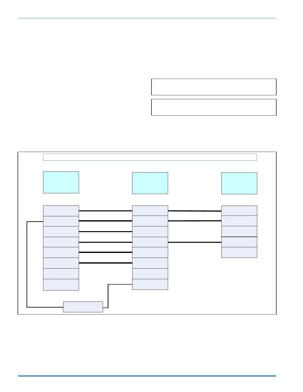
FIGURE 18: Thermostat Chart - Single Stage Air Conditioner with Two Stage Variable Speed Furnace
$
6LQJOH6WDJH$LU&RQGLWLRQHU±7ZR6WDJH9DULDEOH6SHHG)XUQDFH
<
)LUVW6WDJH
&RPSUHVVRU
RU2
5HYHUVLQJ9DOYH
*
)DQ
<
6HFRQG6WDJH
&RPSUHVVRU
5
±9ROW+RW
:
)LUVW6WDJH+HDW
&
±9ROW&RPPRQ
&
±9ROW&RPPRQ
5
±9ROW+RW
<<
)XOO6WDJH&RPSUHVVRU
*
)DQ
7:267$*(
9$5,$%/(
63(('
)851$&(
6,1*/(67$*(
$,5
&21',7,21(5
&
±9ROW&RPPRQ
5
±9ROW+RW
<
)LUVW6WDJH
&RPSUHVVRU
::
)LUVW6WDJH+HDW
7+(50267$7
<
)LUVW6WDJH
&RPSUHVVRU
'(+80
'HKXPLGL¿FDWLRQ
:
6HFRQG6WDJH+HDW
:
9$&+XPLGLVWDW
2SWLRQDO
 Loading...