5750149-UIM-D-1219
36 Johnson Controls Ducted Systems
SECTION IX: SAFETY CONTROLS
CONTROL CIRCUIT FUSE
A 3-amp fuse is provided on the control circuit board to protect the 24-
volt transformer from overload caused by control circuit wiring errors.
This is an ATO 3, automotive type fuse and is located on the control
board.
BLOWER DOOR SAFETY SWITCH
This unit is equipped with an electrical interlock switch mounted in the
burner compartment. This switch interrupts all power at the unit when
the panel covering the blower compartment is removed.
Electrical supply to this unit is dependent upon the panel that covers the
blower compartment being in place and properly positioned.
ROLLOUT SWITCH CONTROLS
These controls are mounted on the burner assembly. If the temperature
in the area surrounding burner exceeds its set point, the gas valve is
de-energized. The operation of this control indicates a malfunction in
the combustion air blower, heat exchanger or a blocked vent pipe con-
nection. Corrective action is required. These are manual reset controls
that must be reset before operation can continue.
PRESSURE SWITCHES
This furnace is supplied with three pressure switches, which monitor the
flow through the combustion air/vent piping and condensate drain sys-
tem. These switches de-energize the gas valve if any of the following
conditions are present. Refer to SECTION VI, "CONDENSATE PIPING
AND FURNACE VENTING CONFIGURATION" for tubing connections.
1. Blockage of vent piping or terminal.
2. Failure of combustion air blower motor.
3. Blockage of combustion air piping or terminals.
4. Blockage of condensate drain piping.
LIMIT CONTROLS
There is a high temperature limit control located on the furnace vesti-
bule panel near the gas valve. This is an automatic reset control that
provides over temperature protection due to reduced airflow. This may
be caused by:
1. A dirty filter.
2. If the indoor fan motor should fail.
3. Too many supply or return registers closed or blocked off.
The control module will lockout if the limit trips 5 consecutive times.
If this occurs, control will reset & try ignition again after 1 hour.
SECTION X: NORMAL OPERATION AND
DIAGNOSTICS
NORMAL OPERATION SEQUENCE
Heating and Cooling Airflow
The heating and the cooling airflows are preset at the factory. The heat-
ing airflow is set to the maximum CFM. The cooling airflow is set to pro-
vide 90 percent of the maximum CFM. The heating and cooling airflows
must be field adjusted to match the HVAC system at installation. See
Table 19 for the HEAT, COOL, and ADJUST (or ADJ) jumper settings to
use for specific airflows.
CFM Board - Delay Taps Selection
The set of jumper pins on the control board labeled DELAY are used to
set the delay profiles for the furnace. These can be chosen so as to
maximize the comfort and sound levels for various regions of the coun-
try.
Tap A is the default profile. It provides a 30-second ramp-up from zero
airflow to full capacity and a 30-second ramp-down from full capacity
back to zero airflow. Whenever there is a change in airflow mode, such
as from low heat to high heat, the motor will take 30 seconds to ramp
from one speed to the other.
Tap B is the humid profile. This profile is best-suited for installations
where the humidity is frequently very high during cooling season, such
as in the southern part of the country. On a call for cooling, the blower
will ramp up to 50% of full capacity and will stay there for two minutes,
then will ramp up to 82% of full capacity and will stay there for five min-
utes, and then will ramp up to full capacity, where it will stay until the
wall thermostat is satisfied. In every case, it will take the motor 30 sec-
onds to ramp from one speed to another.
Tap C is the dry profile. This profile is best suited to parts of the country
where excessive humidity is not generally a problem, where the sum-
mer months are usually dry. On a call for cooling the motor will ramp up
to full capacity and will stay there until the thermostat is satisfied. At the
end of the cooling cycle, the blower will ramp down to 50% of full capac-
ity where it will stay for 60 seconds. Then it will ramp down to zero. In
every case, it will take the motor 30 seconds to ramp from one speed to
another.
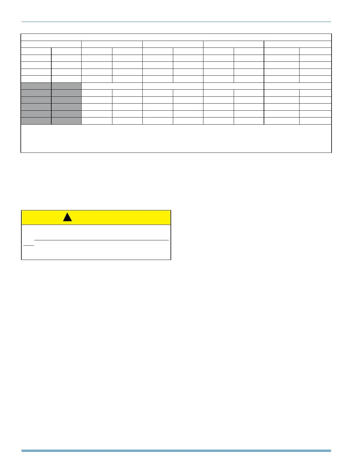
HIGH/LOW HEAT CFM
040A10 060B12 080B12 080C16 Jumper Settings
HIGH HEAT LOW HEAT HIGH HEAT LOW HEAT HIGH HEAT LOW HEAT HIGH HEAT LOW HEAT HEAT Jumper ADJ Jumper
890 770 1200 870 1366 1156 1580 1156 A Any
790 660 1070 770 1293 1022 1422 1027 B Any
711 578 970 693 1185 924 1293 924 C Any
646 514 890 630 1094 840 1185 840 D Any
100C16 100C20 120D20 Jumper Settings
HIGH HEAT LOW HEAT HIGH HEAT LOW HEAT HIGH HEAT LOW HEAT HEAT Jumper ADJ Jumper
1975 1444 1975 1284 2250 1539 A Any
1778 1284 1778 1156 2133 1385 B Any
1616 1156 1616 1050 1939 1259 C Any
1481 1050 1481 963 1778 1154 D Any
All CFM’s are shown at 0.5” w.c. external static pressure.These units have variable speed motors that automatically adjust to provide constant CFM from 0.0” to 0.6” w.c.
static pressure. From 0.6” to 1.0” static pressure, CFM is reduced by 2% per 0.1” increase in static. Operation on duct systems with greater than 1.0” w.c. external static
pressure is not recommended.
NOTE: At some settings, LOW COOL and/or LOW HEAT airflow may be lower that what is required to operate an airflow switch on certain models of electronic air clean-
ers. Consult the instructions for the electronic air cleaner for further details.
* The ADJ “D” tap should not be used.
Table 19: Air Flow Data (Continued)
CAUTION
Main power to the unit must still be interrupted at the main power dis-
connect switch before any service or repair work is to be done to the
unit. Do not rely upon the interlock switch as a main power discon-
nect.
Blower and burner must never be operated without the blower panel
in place.
!