5750149-UIM-D-1219
Johnson Controls Ducted Systems 19
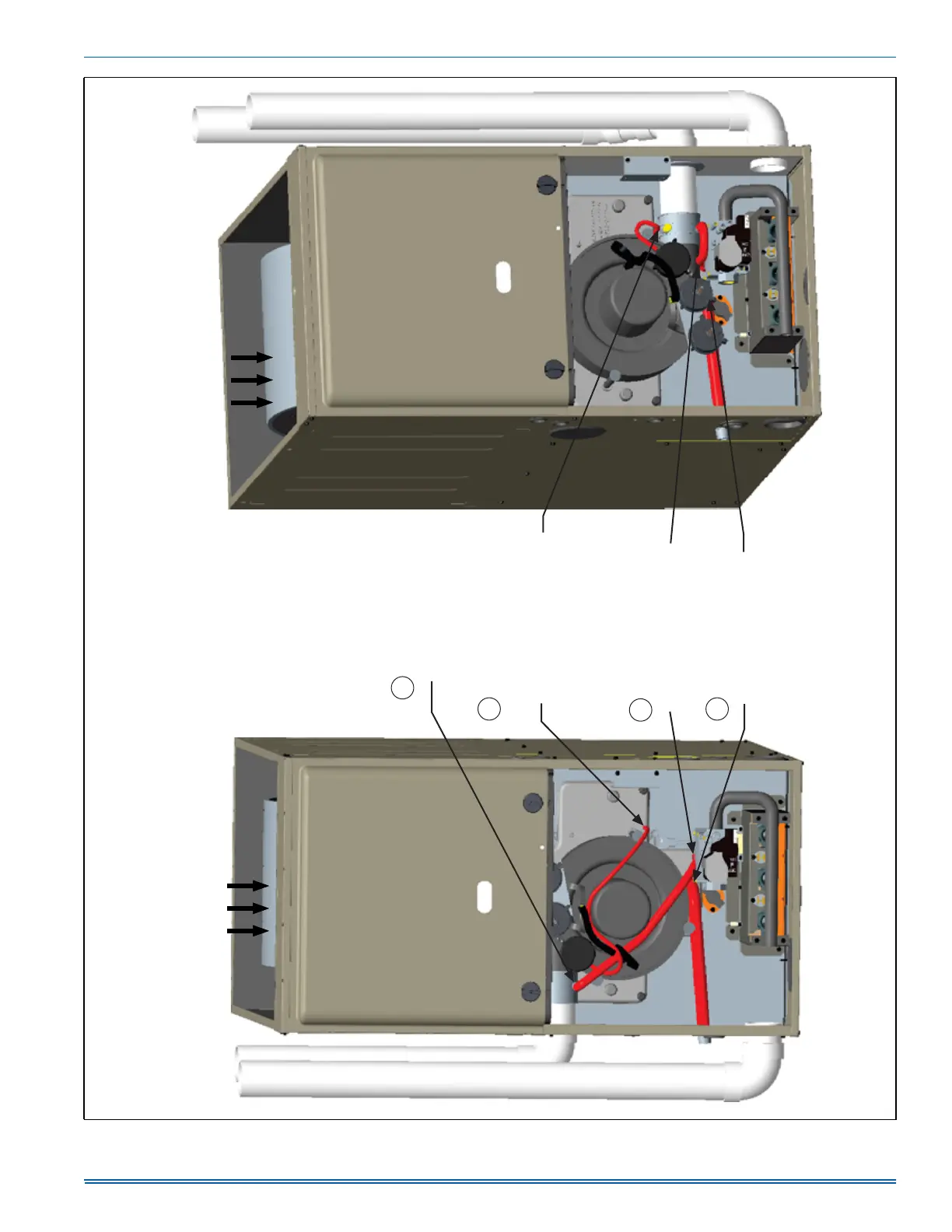
FIGURE 24: Downflow Configuration
AIRFLOW
AIRFLOW
Move rain
gutter hose
to this position.
DOWNFLOW - INDUCER ROTATED
FOR LEFT SIDE VENTING DOWNFLOW - INDUCER ROT
ATED
FOR RIGHT SIDE VENTING
Move pressure switch
hose to this position.
NOTE: May require
the longer hose that
is provided with
wider cabinets.
Move condensate
drain hose to this
position (may exit
either side of the
cabinet).
Move rain gutter
hose to this position.
When drain hose routing changes are required, be sure to cap all un-used openings.
If rerouting hoses - excess length should be cut off so that no sagging loops will collect
and hold condensate, which will cause the furnace to not operate.
1
2
4
3
A0970-001