Form 130.13-NOM1 (114) Supersedes:130.13-NOM1 (808)
Notes:
1. Minimum and maximum airow limits are dependent on the specic DDC controller supplied. Contact the control vendor to obtain the
minimum and maximum differential pressure limits (inches w.g.) of the transducer utilized with the DDC controller.
2. Maximum CFM is limited to value shown in General Selection Data.
3. FlowStar™ differential pressure tubing connections: High side indicated by red tubing; Low side indicated by black tubing.
4. Electric heat will not operate below 0.03” w.g. differential pressure
UNIT
SIZE
400 SERIES
(PNEUMATIC)
STANDARD
CONTROLLER
7000 SERIES
ANALOG
ELECTRONIC
DDC CONSIGNMENT CONTROLS
(See Notes Below)
MIN. MAX. MIN. MAX.
MIN. MAX.
Min. transducer differential
pressure (in. w.g.)
Max. transducer differential
pressure (in. w.g.)
0.015 0.03 0.05 1.0 ≥1.5
10 235 1545 170 1600 170 235 305 1370 1600
12 340 2250 240 2300 240 340 435 1955 2300
14 495 3100 350 3100 350 495 640 2855 3100
16 660 4100 465 4100 465 660 850 3800 4100
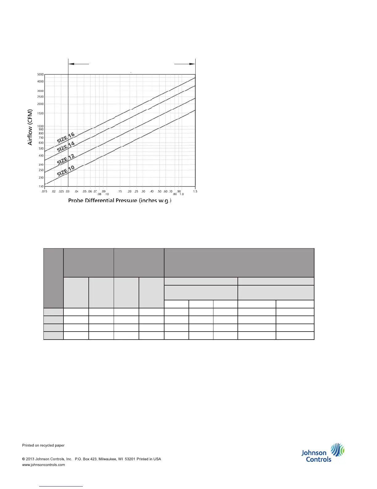
Model TSL
FlowStar Calibration Chart
(For dead-end differential pressure transducers)
NOTE: Maximum and minimum CFM limits
are dependent on the type of controls that are
utilized. Refer to the table below for specic
values. When DDC controls are furnished by
others, the CFM limits are dependent on the
specic control vendor that is employed. After
obtaining the differential pressure range from
the vendor, the maximum and minimum CFM
limits can be obtained from the chart to the left
(many controllers are capable of controlling
minimum setpoint down to 0.015”w.g.)