VA9310 Series Electric Non-Spring Return Valve Actuators Installation Instructions
6
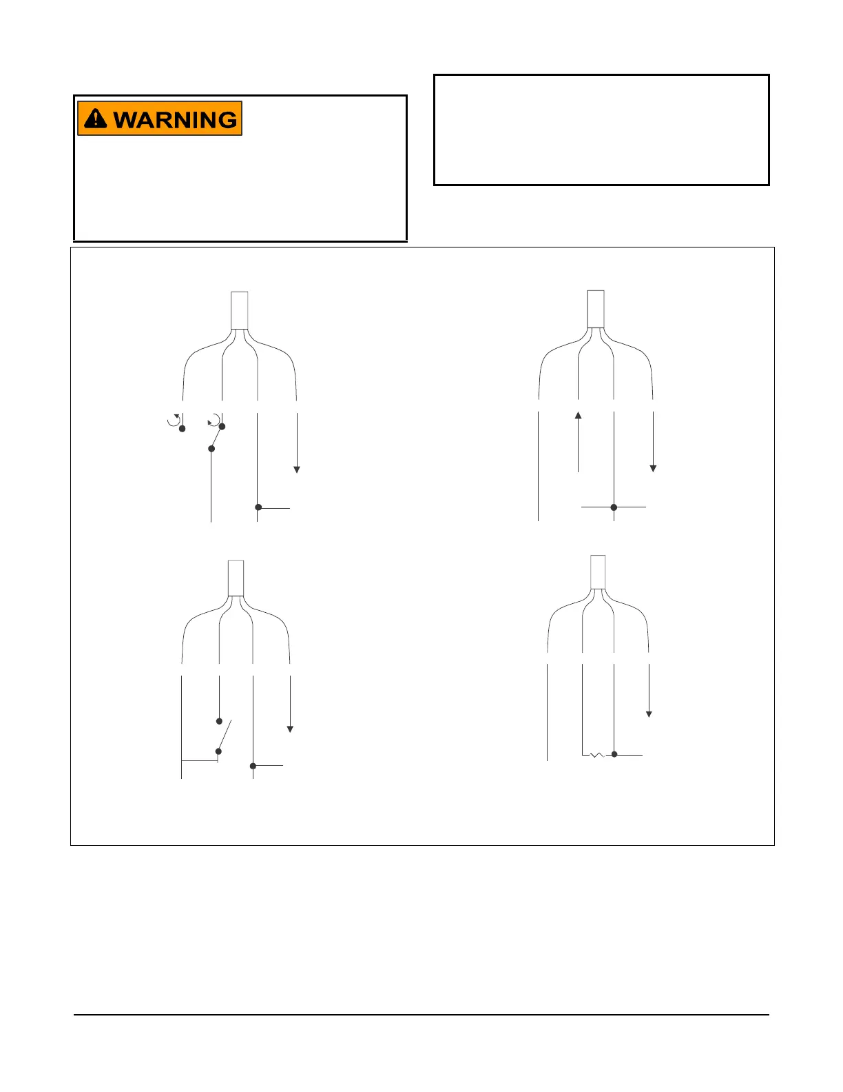
Wiring
VA9310-HGA-2 Actuators Wiring Diagrams
Risk of Electric Shock.
Disconnect the power supply before making electrical
connections. Contact with components carrying
hazardous voltage can cause electric shock and may
result in severe personal injury or death.
IMPORTANT: When using the VA9310-HGA-2
actuator in floating mode, verify that the DIP switch
is positioned on the 2 to 10 VDC option. This setting
ensures compatibility with the controller’s triac
output exhibiting voltage leakage. See Figure 14 for
DIP switch placement.
Figure 9: Floating 24 V Applications
RED
GRY
BLK
ORN
COM
0 to 10 VDC
(-)
24 V AC/DC
(+)
FIG:Floating 24V Applications
Figure 10: On/Off 24 V Applications (See Table 3
for DIP Switch Placement)
RED
GRY
BLK
ORN
24 V AC/DC
24 V AC/DC
COM
0 to 10 VDC
(-)
(+)
FIG:On/Off 24V Applications
Figure 11: Proportional 24 V Applications
RED
GRY
BLK
ORN
24 V AC/DC
0 to 10 VDC
COM
0 to 10 VDC
(-)
(+)
(+)
(-)
FIG:Proportional 24V Applications
Figure 12: Proportional 24 V Applications - 0 (4) to
20 mA with External Resistor
RED
GRY
BLK
ORN
24 V AC/DC
0 (4) to 20 mA
COM
0 to 10 VDC
(-)
(+)
(+)
FIG:Control with External Resistor
500 ohm,
1.4 W