VA9310 Series Electric Non-Spring Return Valve Actuators Installation Instructions
7
Auto Calibration Mode
The actuator enters auto calibration mode and
positions the valve shaft to the maximum and minimum
end stops to identify the range of travel.
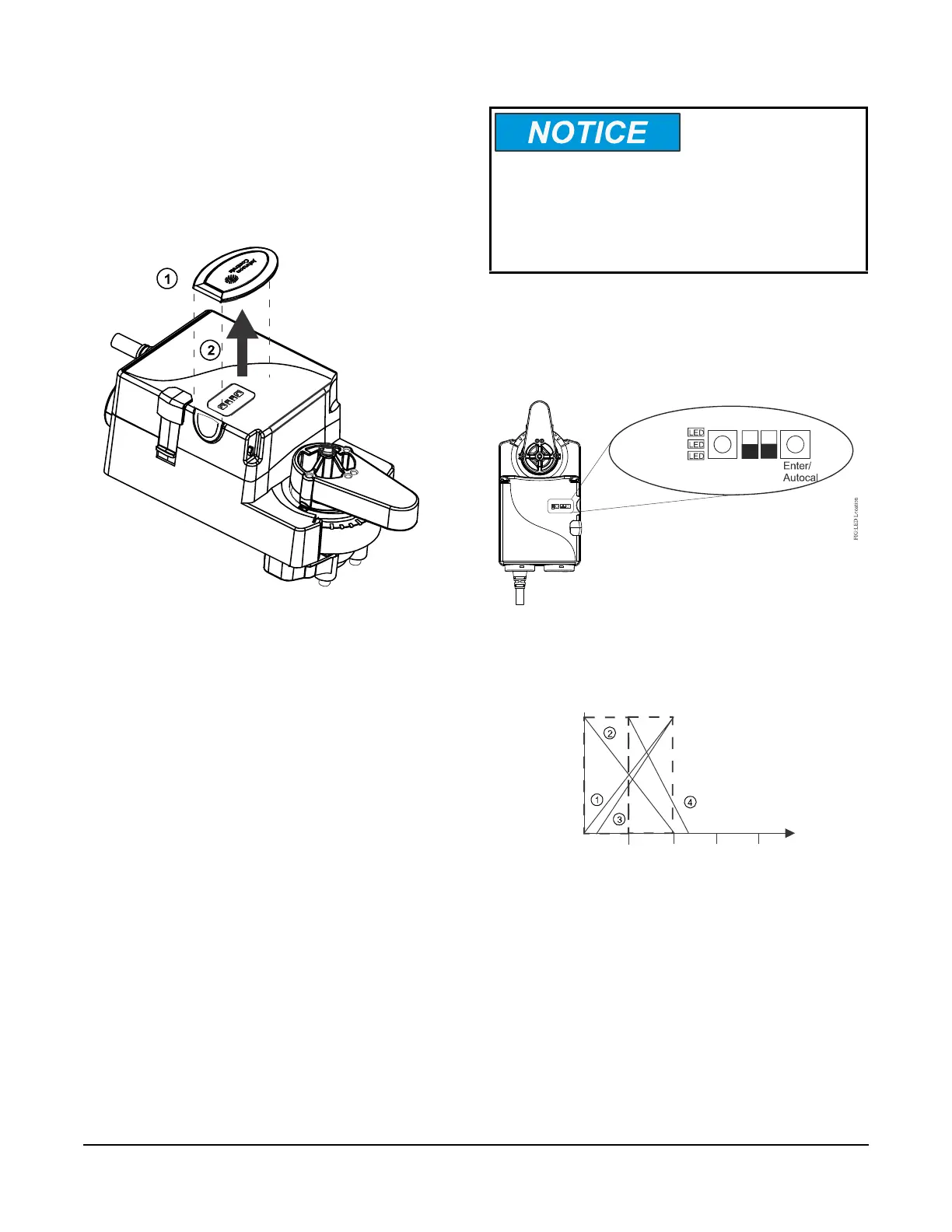
Accessing the DIP Switches and LEDs
Locate the oval cover on the front of the unit and pull
the cover outward.
To complete the auto calibration process, press
Enter/Autocal until all three LEDs are on. See
Figure 14 for viewing the DIP switches and LEDs.
Operation
The valid Offset values are 0 to 10 VDC, and the valid
Span values are 2 to 10 VDC. The maximum feedback
voltage of the actuator is 10 VDC.
Figure 13: DIP Switch and LED cover
FIG:LED ans DIP Switch Cover
Risk of Property Damage.
Do not apply power to the system before checking all
wiring connections. Short circuited or improperly
connected wires may result in permanent damage to
the equipment.
Figure 14: DIP Switches and LEDs Placement
Span Adj.
Offset Adj.
INC.
DA
0-10
RA 2-10
VA9310-HGA-2
Figure 15: Graphed Examples of Table 3
Command Signals
Max.
10 VDC
FIG:Example Graph
Min.
20 VDC0 VDC
Stroke
 Loading...


