VA9310 Series Electric Non-Spring Return Valve Actuators Installation Instructions
9
Clearing the SPAN and OFFSET Proportional
Command Signal Voltage Setting
Cycle DIP switch two between 2 to 10 and 0 to 10. The
active setting is the final state of DIP switch two.
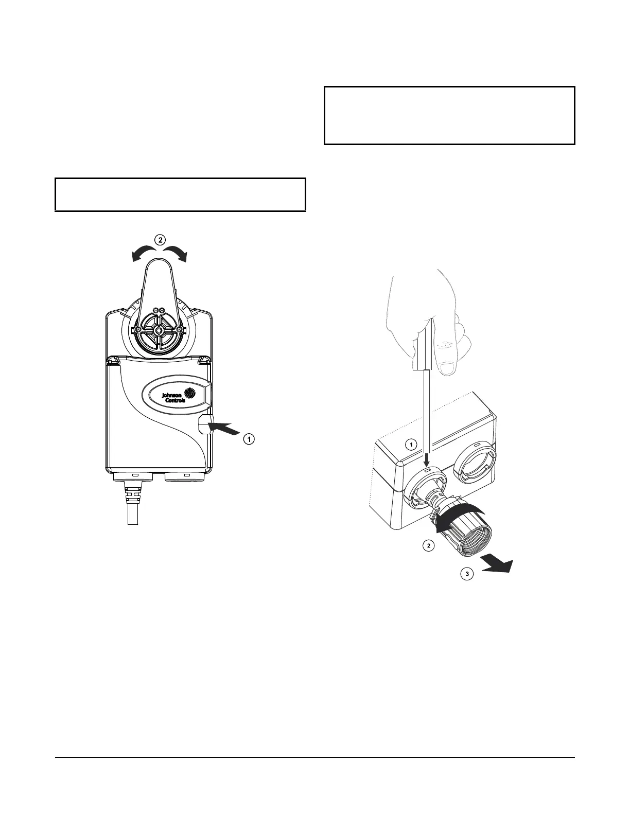
Repositioning the Actuator Hub
1. De-energize the actuator.
2. Press the black manual override button on the side
of the housing.
3. Rotate the tab to the desired po
sition.
Installing the Cover over the DIP Switches and
LEDs
Removing the Conduit Connector
You can remove the conduit connector at the bottom of
the unit if the connector is damaged. To remove the
connector:
1. Insert a 1/8 in. (3 mm) screwdriver into the slot on
the housing.
2. Rotate the conduit connector counterclockwise a
nd
r
emove it from the actuator.
Repair Information
If the VA9310 Series Electric Non-Spring Return Valve
Actuator fails to operate within its specifications,
replace the unit. For a replacement valve actuator,
contact the nearest Johnson Controls® representative.
IMPORTANT: The manual override is automatically
released when the button is released.
Figure 16: Override Button
IMPORTANT: Once you have verified the DIP
switch placement and LED activity, place the oval
cover back onto the unit before repositioning the
actuator hub.
Figure 17: Removing the Conduit Connector
 Loading...


