VA9310 Series Electric Non-Spring Return Valve Actuators Installation Instructions
8
Setting the SPAN and OFFSET Proportional
Command Signal to Other Values
1. Set DIP switch one and two before proceeding.
See
Figure 14 for DIP switch placement.
2. Connect a digital multimeter between the orange
(feedback) and black (common) wires. See Wiring
for mo
re wiring information.
3. Press Enter/Autocal.
To adjust the span and offset, press but do not ho
ld
Ente
r/Autocal. Holding Enter/Autocal for
longer
than 3 seconds triggers an autocal.
The Offset Adj. LED turns on, and the multimeter
displays the current offset value.
4. Press INC.
The Offset Adj. LED flashes. The voltage readin
g
on the
multimeter increases 0.5
VDC each time
yo
u press the button. Press INC. until you reac
h
t
he desired voltage.
If no further action is required, the Offset
Adj. LED
stop
s flashing after 10 seconds. The actuator exit
s
th
e program mode, and the original offset valu
e
re
mains unchanged.
5. Press Enter/Autocal
.
The
Offset Adj. LED turns off indicating that th
e
desir
ed Offset Adj. value was recorded. The Span
Adj. turns on, and the multimeter displays the
present SPAN value.
6. Press INC.
The Span Adj. LED flashes. The voltage reading
on
th
e multimeter increases by 0.5 VDC each time
you press the button. Press INC. until you reac
h
t
he desired voltage.
If no further action is required, the Offset an
d Adj.
LED
stops flashing after 10 seconds. The actuator
exits the program mode, and the original offset
value remains unchanged.
7. Press Enter/Autocal.
The Span Adj. LED turns off indicating that th
e
desir
ed Span Adj. setting is saved, a
nd the
actu
ator exits the program mode.
Reading the SPAN and OFFSET Proportional
Command Signal Voltage Settings
1. Connect a digital multimeter between the orange
(feedback) and black (common) wires. See Wiring
for more wiring information.
2.
Press Enter/Autocal.
The Offset Adj. LED turns on, and the multimeter
displays the current offset value.
3. Press Enter/Autocal.
The Offset Adj. LED turns off, the Span Adj. LED
turns on, and the multimeter displays the pres
ent
SP
AN value.
4. Press Enter/Autocal.
The Span Adj. LED turns off.
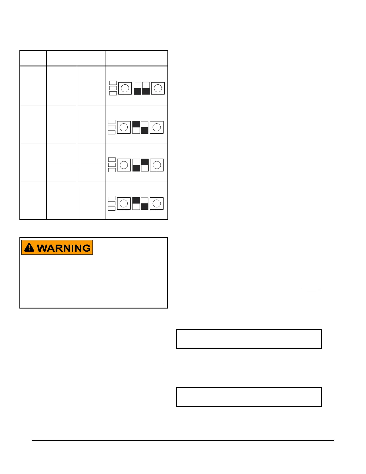
Table 3: DIP Switch Settings
Example Command
Signal
Feedback
Signal
Settings VA9310-HGA
User Interface
1 0 to 10
VDC
Direct
0 to 10
VDC
2 0 to 10
VDC
Reverse
0 to 10
VDC
3 2 to 10
VDC
Direct
2 to 10
VDC
24 VAC –
4 Offset = 5
Span = 7
Reverse
10 to 2
VDC
Risk of Electric Shock.
Do not touch any exposed metal parts with anything
other than properly insulated tools or insulated probes
of the digital voltage meter. Failure to use properly
insulated tools and probes may result in severe
personal injury or death.
IMPORTANT: Do not press INC. Otherwise your
observed offset voltage setting changes.
IMPORTANT: Do not press INC. Otherwise your
observed SPAN voltage setting changes.
 Loading...


