VFD66 User Guide 29
Issue Number: 2 www.johnsoncontrols.com
Safety information Rating data
Mechanical
installation
Electrical
installation
De-rating
Keypad and
display
Parameters
Diagnostics
Technical
specifications
UL Listing
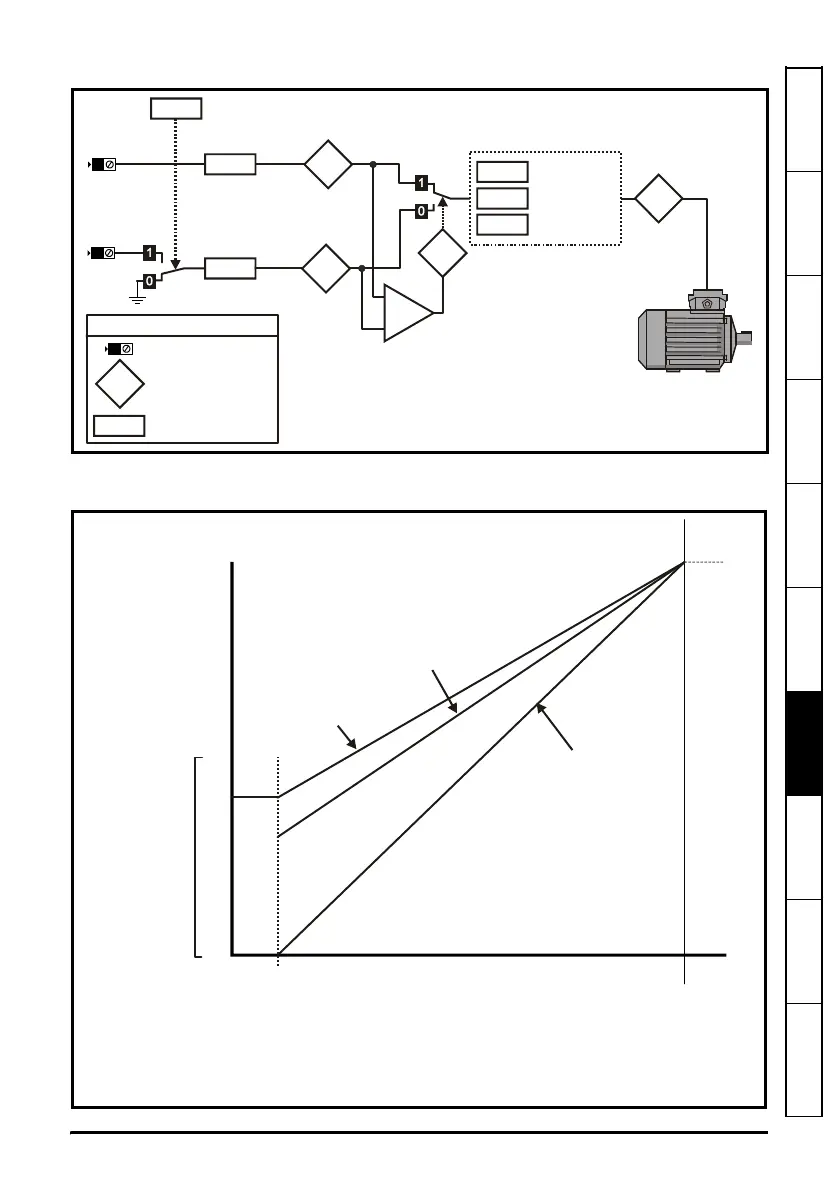
Figure 7-2 Standard input mode Pr 05 = Std
The Proportional band of the drive will be between the values selected in Pr 67
(0 to 50%) and Maximum speed Pr 02.
4
5
65
95
94
+
_
85
66
65
Analog
input 1
2 transducer
Input voltage
level 5/10V
Analog
input 1
Analog
input 2
Comparator,
higher of the
two is selected
Motor
frequency
Input voltage
level 5/10V
Analog
input 2
63
Input terminals
Read-write parameter
Read-only parameter
Key
XX.XX
XX.XX
X
Minimum speed
67
64
02
Action at min.
pressure
Max speed
Minimum motor speed set by Pr
67
Analog input
RPM
10%
20%
30%
40%
50%
100%
Curve B:
67
64
0%
Curve C:
Pr = 0%
Pr = stop/hold
67
64
Curve B:
Pr = Stop
Motor shuts off at the minimum
speed set by Pr (30% of max
speed)
64
67
Curve C:
Pr = Hold or Stop
Motor shuts off at the minimum
speed set by Pr (0% of max
speed)
64
67
Curve A:
Pr = Hold
Motor Idles at the minimum speed
set by Pr (40% of )
64
67
max speed
Curve A:
Pr = 40%
Pr = hold
67
64
0% 10% 20% 40% 60% 80% 90% 100%