Powered by
Eaton’s Technology VSD Series Quick Start Guide
LIT-1201858
For more information visit: www.johnsoncontrols.com 11
November 2009
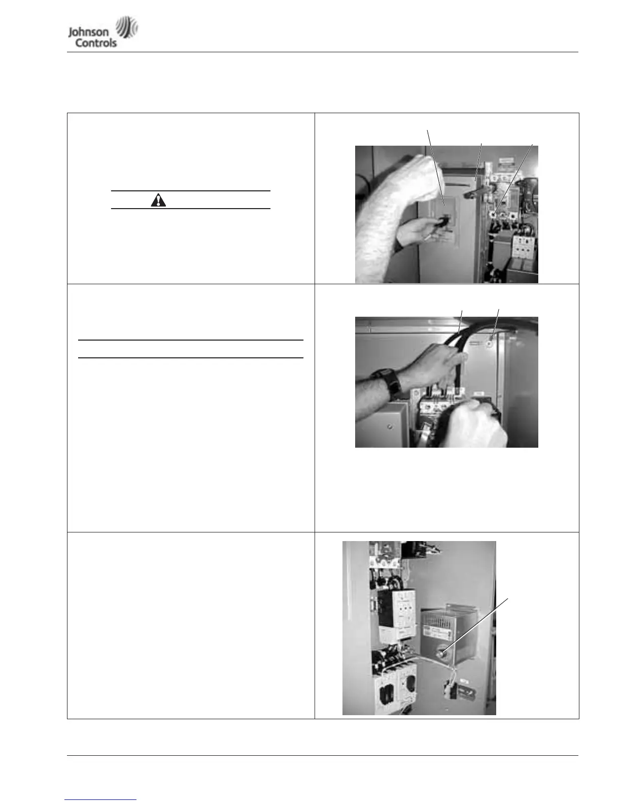
Enclosed NEMA Type 12/3R
Table 6: Bypass Power Wiring Instructions — NEMA Type 12/3R
Mounting Drive
1. Mount drive per dimensions. (See Page 10.)
2. Verify that the main power source is removed upstream.
3. Remove the keypad cable from the drive.
4. Remove the screws from the drive cover, and remove the
cover.
The circuit breaker extension bar is sharp and can cause injury.
5. Calibrate the circuit breaker amperage, so it is 1.25 times
the value on the motor nameplate, by turning the red set
screw located below the circuit breaker extension bar. See
the circuit breaker user’s manual supplied with the drive.
Power and Ground Wiring
6. Using a Greenlee conduit cutter (recommended), cut three
holes in the drive’s enclosure for the incoming power,
motor and low-voltage control leads.
Note: Power, motor and control leads must each be
located in separate conduit.
• DO NOT RUN CONTROL WIRING in same conduit
with power wiring.
• Provide low impedance ground connection to drive
chassis.
• DO NOT CONNECT B+, B-, R terminal.
(Reserved for Braking Resistor only.)
7. Connect the incoming power leads to circuit breaker
terminals labeled L1, L2 and L3.
8. Using the torque wrench, tighten each terminal to
the torque value found in the appropriate user’s
manual supplied with the drive.
9. Connect the power ground wire to the ground stud.
Connect motor ground to ground stud.
Setting Space Heater
10. If applicable, set the space heater. See the space heater
user’s manual supplied with the drive.
Note: The space heater is used to prevent condensation from
damaging the equipment when the drive is not operating
(OFF).
CAUTION
Circuit
Breaker
Set Screw
Circuit
Breaker
Extension Bar
Keypad Cable
POWER WIRING
Power
Ground Wire
Incoming
Power Leads
Space Heater
Temperature
Setting
 Loading...


