VSD Series Quick Start Guide Powered by
Eaton’s Technology
20 For more information visit: www.johnsoncontrols.com LIT-1201858
November 2009
Appendix F — Main Menu Navigation
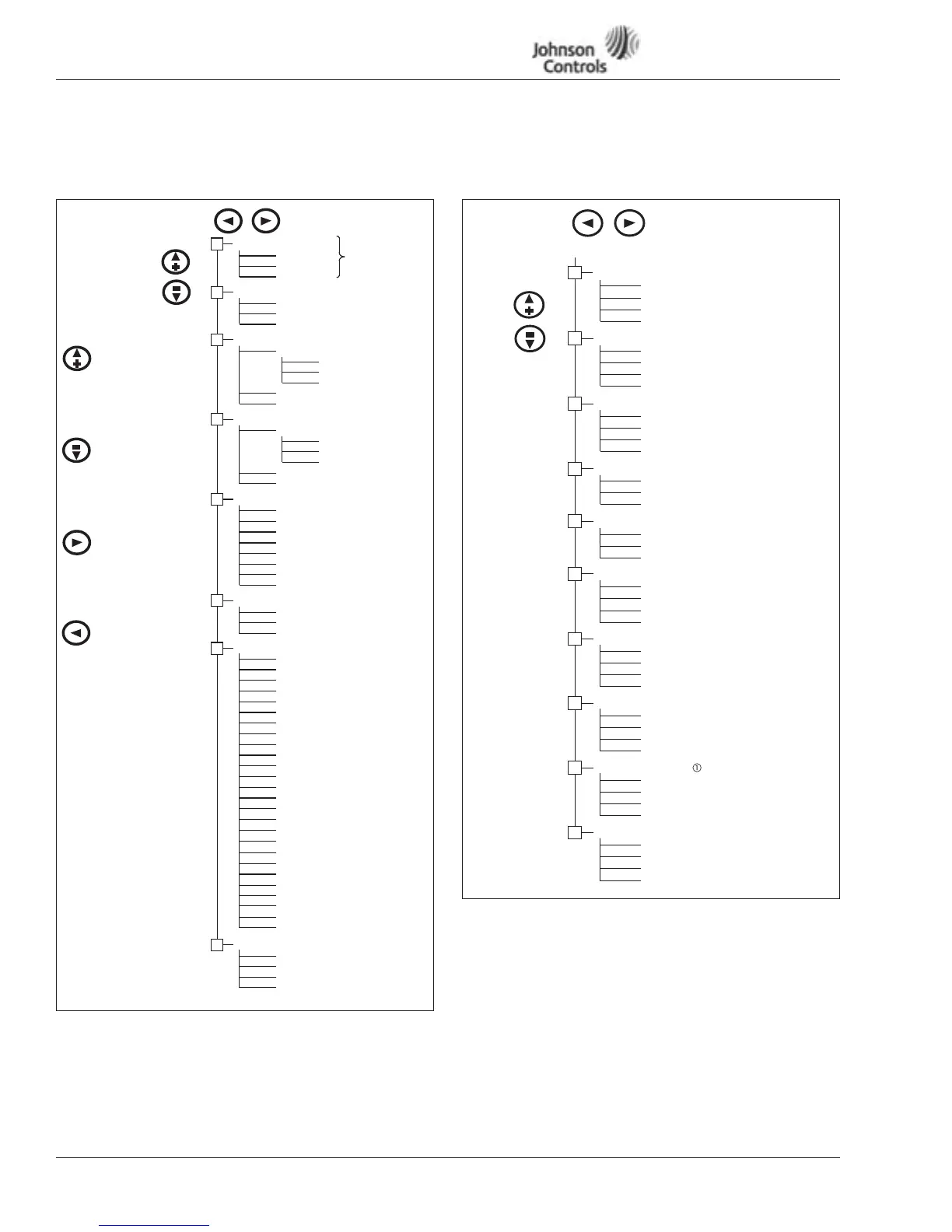
Main Menu Navigation
Figure 19: Main Menu Navigation
Parameter Menu Structure Example
Figure 20: Parameter Menu Structure Example
M1 Programming
M2 Keypad Control
M3 Active Faults
M6 Expander Boards
M7 Monitor
G1.1
. . .
. . .
R2.1 Keypad Reference
P2.x Stop Button Active
A3.1 Active Fault 1
T3.1.1 Operation Days
. . .
T3.1.13 Zero Speed
A3.x Active Fault x
V7.1 Actual Speed
V7.2 Output Frequency
V7.3 Speed Setpoint
G1.x
G6.1 Slot A Board
. . .
G6.5 Slot E Board
+
+
+
+
V7.4 Motor Speed
V7.5 Motor Current
V7.6 Motor Torque
V7.7 Motor Power
V7.8 Motor Voltage
V7.9 DC-Bus Voltage
V7.10 Unit Temperature
V7.11 Motor Temperature
V7.12 (A) AI-1
V7.13 (A) AI-2
V7.14 DI-1 DI-2 DI-3
V7.15 DI-4 DI-5 DI-6
V7.16 DO-1 RO-1 RO-2
V7.17 (A) AO-1
V7.18 ActFaultCode
Menu Navigation:
The up arrow advances
to the next menu item.
For example, pressing the
up arrow once will
advance from M1 to M2.
The down arrow backs up to
The right arrow will advance
the previous menu item.
to the next level in the menu.
The left arrow will back up
one level in the menu structure.
For example, pressing the
down arrow once will back
up from M2 to M1.
For example, pressing the
right arrow once will
advance from M2 to R2.1.
For example, pressing the
left arrow once will back
up from R2.1 to M2.
V7.19 ActWarnCode
V7.20 Status Word
V7.21 PI-Setpoint
V7.22 PI-Input
V7.24 PI-Output
V7.23 PI-Error
M8 Operate Mode
O1 Output Frequency
O2 Actual Speed
. . .
Ox Motor Temperature
+
G7.26 Multimonitor
V7.25 RO-1 RO-2 RO-3
+
+
M5 System Menu
S5.1 Language
S5.2 Application
S5.3 Copy Parameters
+
S5.4 Compare Parameters
S5.5 Security
S5.6 Keypad Settings
S5.7 Hardware Settings
S5.8 System Information
. . .
M4 Fault History
H4.1 Most Recent Fault
T4.1.1 Operation Days
. . .
T4.1.13 Zero Speed
H4.1.x Oldest Saved Fault
. . .
Up Arrow
Down Arrow
Right Arrow
Left Arrow
See Figure 3.
G1.1 Quick Setup
G1.2 Input Signals
G1.3 Output Signals
G1.6 Motor Control
G1.7 Protections
G1.8 Fieldbus
P1.1.1 Minimum Frequency
. . .
. . .
P1.2.1 Start Mode
P1.2.2 Intlk Timeout
P1.2.15 Setpoint Scale Max
P1.3.1 (A) AO-1 Function
P1.7.1 Input Phase Supv
P1.7.2 4 mA Fault Response
. . .
P1.1.26 PI-Contr. I-Time
P1.6.1 Motor Control Mode
. . .
P1.6.12 Identification
P1.8.1 FB Data Out 1
P1.8.2 FB Data Out 2
. . .
P1.8.8 FB Data Out 8
+
+
+
P1.3.2 (A) AO-1 Filter
P1.3.21 Start Relay OFF Delay
. . .
P1.4.1 Start Function
P1.4.2 Stop Function
P1.4.3 Brake Choppper
P1.7.19 Automatic Restart
P1.1.2 Maximum Frequency
+
+
+
+
G1.9 PI-Control
G1.10 Preset Speed
P1.9.1 Setpoint Min
P1.9.2 Setpoint Max
. . .
P1.9.14 Auto S-Curve Time
+
P1.10.1 Preset Speed 1
P1.10.2 Preset Speed 2
. . .
P1.10.7 Preset Speed 7
+
M1 Programming Menu
P1.6.2 V/Hz Optimization
G1.5 Prohibit Frequency
P1.5.1 Range 1 Low Limit
. . .
+
P1.5.13 PH Acc/Dec Ramp
G1.4 Drive Control
 Loading...


