VSD Series Quick Start Guide Powered by
Eaton’s Technology
18 For more information visit: www.johnsoncontrols.com LIT-1201858
November 2009
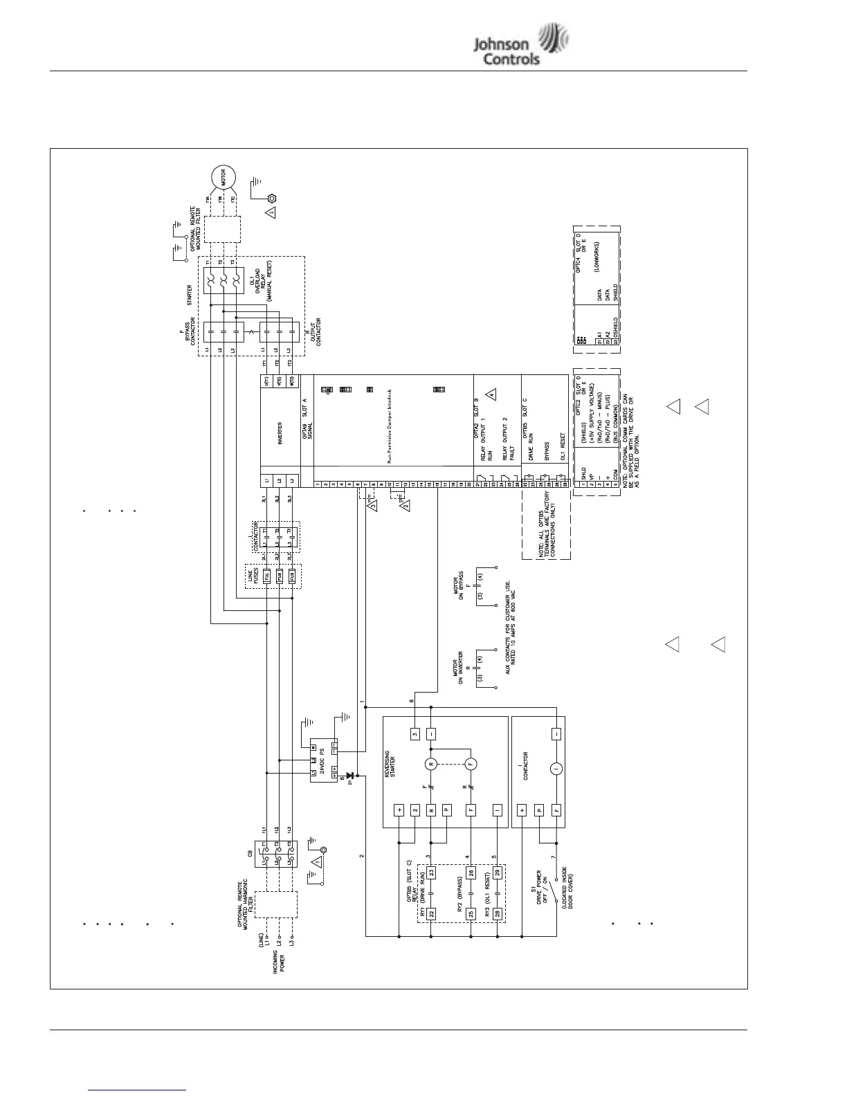
Appendix D — Bypass Wiring Diagram
Figure 16:
Incoming Power Connection Notes: Motor Connection Notes:
I/O Connection Notes:
Run 110 Vac and 24 Vdc Control Wiring
in Separate Conduit.
Communication Wire to be Shielded.
RS-232 Keypad Cable Less Than 20 Feet.
Notes:
Enclosure and Motor(s) Must be Grounded.
See Instruction Manual. A continuous wire
must be run from drive to motor.
Jumper is Factory Installed to Enable
Start Permissive. Can be Replaced with
N/C Contact.
Close Terminals 6 to 8 or 8 to 12
to Start VFD in Auto Mode.
Relays Shown in De-Energized State.
1
2
3
4
Drive
Ground
Motor
Ground
Customer
Ground
Drive
Ground
Run Cabling in Separate Metal Conduit or Wire Tray.
Do Not Run With Control Wiring or Motor Cables.
Cables to be Sized per NEC.
Provide Low Impedance Ground Connection to
Drive Chassis.
Do Not Connect to B+, B-, R Terminals. These
Terminals are Used for External Braking or Single-
Phase Capacitors.
Run Motor Cables in Separate Metal Conduit or
Wire Tray.
Do Not Run with Control Wiring or Power Cables.
Cables to be Sized per NEC.
Provide Low Impedance Ground Connection Between
and Drive.
+1DV
Vin+
GND
Lin+
Lin–
24Vout
GND
DIN1
DIN2
DIN3
CMA
24Vout
GND
DIN4
DIN5
DIN6
CMB
Lout+
Lout–
DO1
Reference Output
I/O Ground
Control Voltage Output
I/O Ground
External Fault
DIN1-DIN3 Common
Control Voltage Output
I/O Ground
Bypass Overload Fault
DIN4-DIN6 Common
Output Frequency
Analog Output
Digital Output Ready
X1
X2
X3
A
B
C
D
A
B
C
D
X6
A
B
C
D
Analog Input Voltage
(Range 0-10V DC)
Analog Input Current
(Range 4-20mA)
Speed Select 1
Fire Mode
Start/Stop
OptionalOptional
Note: See Figure 3
for Dip X1, X2,
X3, X6 Switch
settings.
 Loading...


