Powered by
Eaton’s Technology VSD Series Quick Start Guide
LIT-1201858
For more information visit: www.johnsoncontrols.com 25
November 2009
Appendix H — Static Checking
Static Checking
Static checking tests the integrity of the power-carrying components (diodes, capacitors
and IGBTs) within the drive assembly. Performing these static checks ensures that no
damage occurred during shipping or installation that could cause a failure when the drive
is powered.
Make sure there is no power to the drive before proceeding with any of the static checks.
After checking each set of terminals, zero out the multimeter by touching the metal tips of
the red (positive) and black (negative) leads to each other.
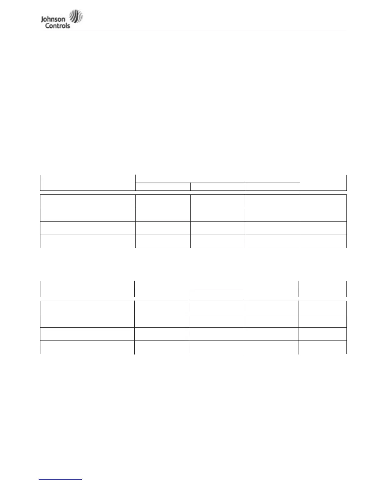
Note: Set the multimeter to the diode function, and check each power terminal
consecutively with each DC bus terminal as indicated in Table 7.
Table 7: Static Checks of Converter
Note: Set the multimeter to the diode function, and check each motor terminal
consecutively with each DC bus terminal as indicated in Table 8.
Table 8: Static Checks of Inverter
DC Bus Terminal Power Terminal Multimeter
Reading
L1 L2 L3
B+ (1st Overload Check)
Insert red (+) multimeter lead.
Insert black (-)
multimeter lead.
Insert black (-)
multimeter lead.
Insert black (-)
multimeter lead.
.OL
B- (2nd Overload Check)
Insert black (-) multimeter lead.
Insert red (+)
multimeter lead.
Insert red (+)
multimeter lead.
Insert red (+)
multimeter lead.
.OL
B- (1st Voltage Check)
Insert red (+) multimeter lead.
Insert black (-)
multimeter lead.
Insert black (-)
multimeter lead.
Insert black (-)
multimeter lead.
.25 – .55V DC
(±10%)
B+ (2nd Voltage Check)
Insert black (-) multimeter lead.
Insert red (+)
multimeter lead.
Insert red (+)
multimeter lead.
Insert red (+)
multimeter lead.
.25 – .55V DC
(±10%)
DC Bus Terminal Motor Terminal on Contactor if Bypass or Output Contactor Multimeter
Reading
T1 T2 T3
B+ (1st Overload Check)
Insert red (+) multimeter lead.
Insert black (-)
multimeter lead.
Insert black (-)
multimeter lead.
Insert black (-)
multimeter lead.
.OL
B- (2nd Overload Check)
Insert black (-) multimeter lead.
Insert red (+)
multimeter lead.
Insert red (+)
multimeter lead.
Insert red (+)
multimeter lead.
.OL
B- (1st Voltage Check)
Insert red (+) multimeter lead.
Insert black (-)
multimeter lead.
Insert black (-)
multimeter lead.
Insert black (-)
multimeter lead.
.25 – .40V DC (±10%)
B+ (2nd Voltage Check)
Insert black (-) multimeter lead.
Insert red (+)
multimeter lead.
Insert red (+)
multimeter lead.
Insert red (+)
multimeter lead.
.25 – .40V DC (±10%)
 Loading...


