VSD Series Quick Start Guide Powered by
Eaton’s Technology
26 For more information visit: www.johnsoncontrols.com LIT-1201858
November 2009
Appendix H — Static Checking, continued
Note: Set the multimeter to the ohm function, and check the power gµround terminal and
DC bus terminals as indicated in Table 9.
Note: Frame 6 and larger use a “Hybrid” rectifier section. “Shown in Service Manual.”
Readings will be different when taking measurements from (B+) DC.
Table 9: Static Checks of DC Bus
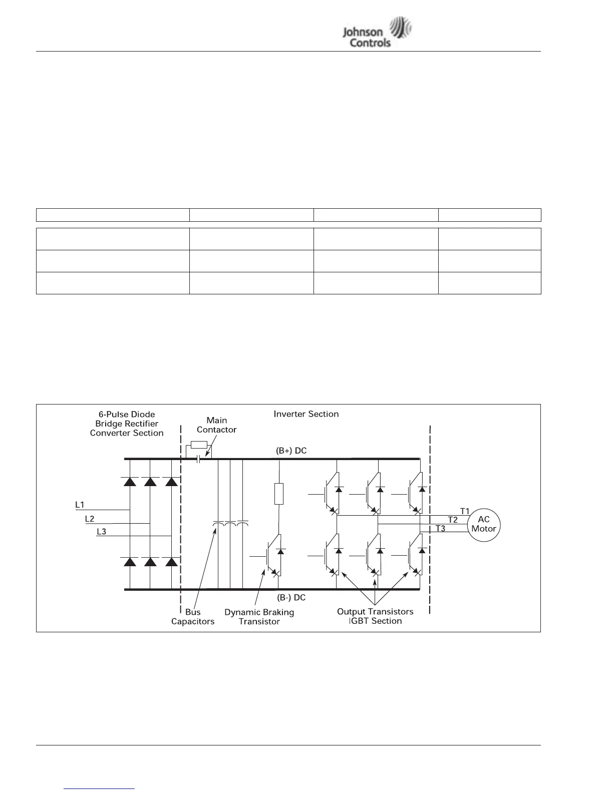
Figure 25 is a detailed schematic to aid in performing the static checks.
Continuity Test to Ground
Test L1, L2, L3 to ground.
T1, T2, T3 to ground.
This should read .OL ohms.
Figure 25: Schematic for Static Checks (Sample for Frames 4 and 5)
DC Bus Terminal DC Bus Terminal (B-) Ground Terminal (Power) Multimeter Reading
B+ (Overload Check)
Insert red (+) multimeter lead.
Insert black (-) multimeter lead. Not used. .OL
B+ (1st Ohm Check)
Insert black (-) multimeter lead.
Not used. Insert red (+) multimeter lead. O.L
B- (2nd Ohm Check)
Insert black (-) multimeter lead.
Not used. Insert red (+) multimeter lead. O.L
 Loading...


