Powered by
Eaton’s Technology VSD Series Quick Start Guide
LIT-1201858
For more information visit: www.johnsoncontrols.com 17
November 2009
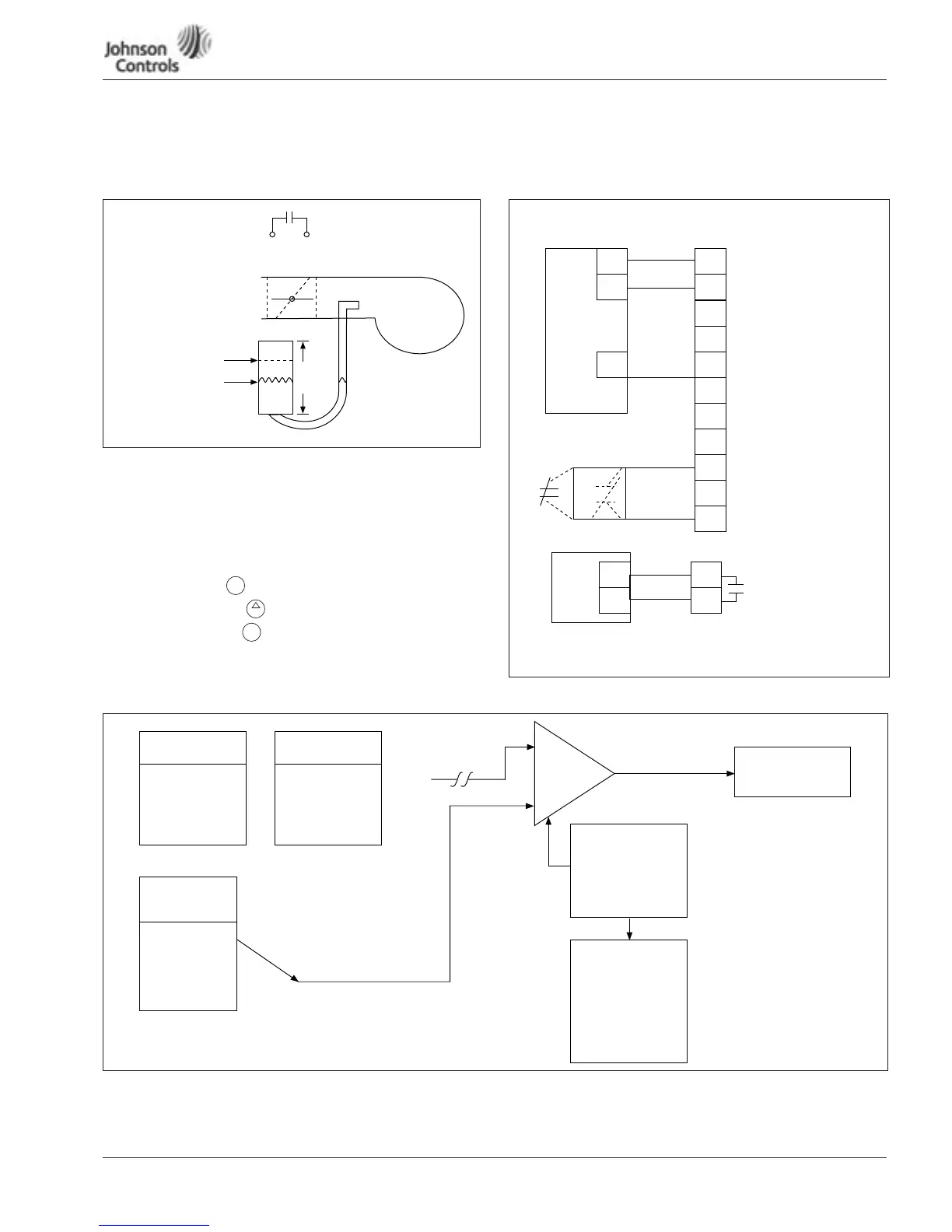
Appendix C — Interlock Damper Start Example
Interlock Damper Start Example Using PID Duct Static Control Signal
Figure 13: Interlock Damper Start with PID Duct Static Example
Step 1. Wire load line, digital I/O per example and verify
voltage and amperage
Step 2. Static check drive SCR, IGBT, DC Bus per Static Check,
Page 20 and 21
Step 3. Start-up wizard (Duct static application)
Step 4. Select hand to check motor rotation
Step 5. Press Start and to increase speed in Hand mode
Step 6. Select Remote to run in Auto
Step 7. Tune PID per diagram below
Figure 14:
Figure 15: PID Flow Chart
Max WC = 2.5”
Main WC = 0.0”
Setpt WC = 2.0“
To Drive Damper
Interlock Terminals
10 12
Fan
Set PT Keypad Default
Actual PI Feedback
A1-1, 0-10 Vdc Default
2.50”
Water
H
2
O
Error
HOA
+
HOA
2
3
2
3
6
6
8
10
12
0 ñ 10 Vdc
Actual
+
-
24 Vdc
Out
Com
Power
Pressure
X Drive
Factory
Jumper
22
23
A1-1+ 0 ñ 10 Vdc
A1-1- Default
24 Vdc Control
Close Terminal
(6 ñ 8) to Start VFD
D1-1
D1-3 Run Permisive
Damper Interlock
(Default)
24 Vdc Control Voltage
Closed on
Run
Default
8 A/24 Vdc
.8 A/125 Vac
.4 A/250 Vac
OPTA9 Slot A
OPTA2 Slot B
Damper Actuator
Input Terminals
Hand Mode (M1)
P1.1.13
A1 - 1
A1 - 2
Keypad
Motor Pot
Actual PI (M1)
Feedback
P1.1.17
A1 - 1
A1 - 2
Fieldbus
Min A1-1, A1-2
Max A1-1, A1-2
Ave A1-1, A1-2
Auto Mode (M1)
P1.1.15
A1 - 1
A1 - 2
Keypad
Motor Pot
Fieldbus
PID Gain (M1)
P1.1.20
PID I-Time
P1.1.21
PID Control D
P1.1.22
Output
Frequency
PI
Error
Amp
PI Setpoint
PI Ref Rise T
P1.1.23
PI Ref Fall Time
P1.1.24
PI Ref Max
P1.1.19
PI Ref Min
P1.1.18
OR
P10 Parameter
Adjustments
Sensor
Output
Signal
Sensor Parameter
Adjustments
 Loading...


