Powered by
Eaton’s Technology VSD Series Quick Start Guide
LIT-1201858
For more information visit: www.johnsoncontrols.com 15
November 2009
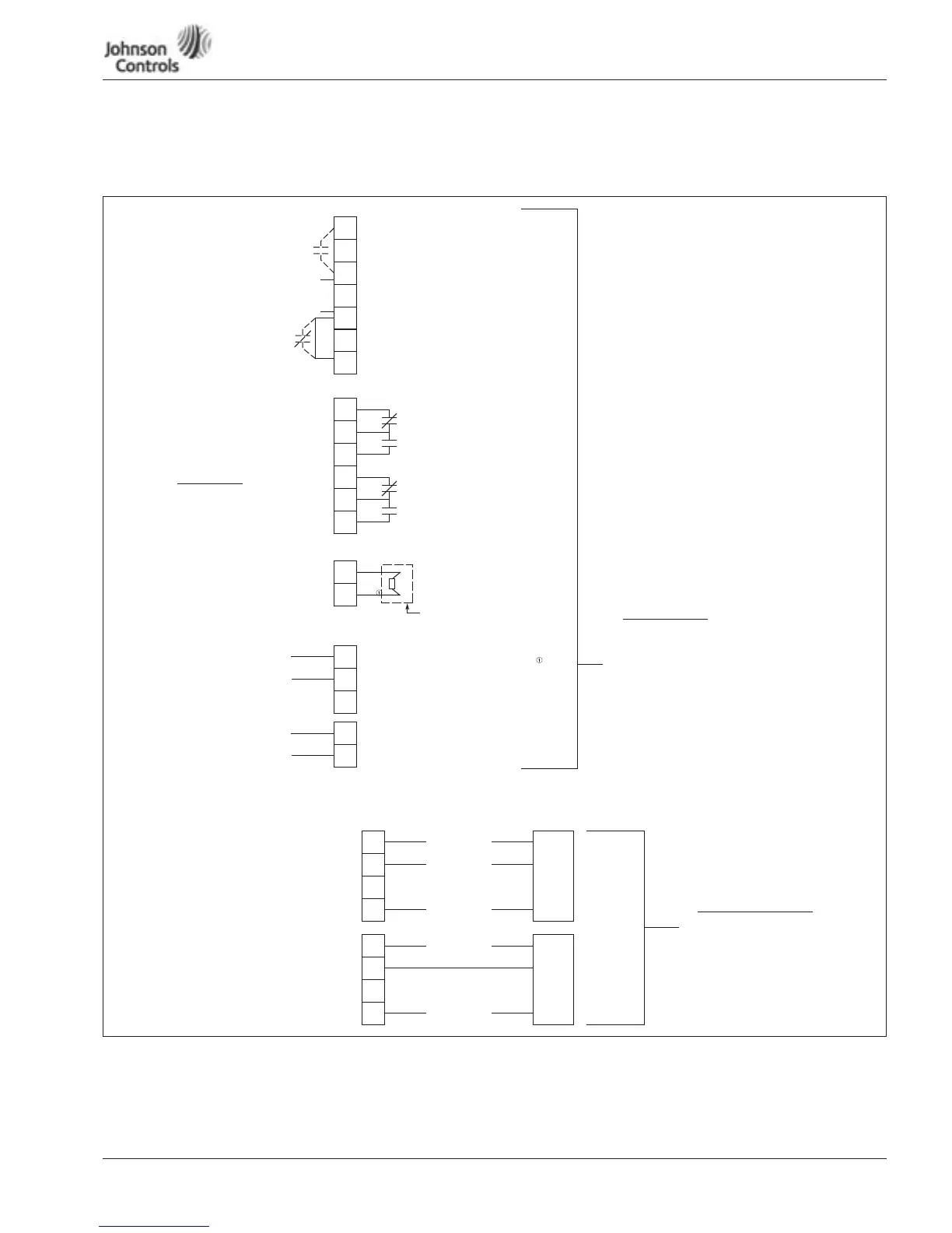
Appendix A — Main Control Board Wiring
Main Control Board Wiring Default in Slot A and B
Figure 10: Wiring Diagrams (Default)
Card is programmable for a 0 – 10V DC with change in jumper. Add X6 jumper on Board A6 from A-B to C-D.
Digital Input
24V DC
OPTA9 Slot A
+
24V DC
+
24V DC
6
Control Relay
Outputs
OPTA2 Slot B
8A / 24V DC
.4A / 125V DC
.8A / 250V AC
Continuous Capacity
≤
2 RMS
CR Ratings
21
22
23
24
25
26
(22-21) Opens on Run (Default)
Remote Input
Duct Static
Building Static
Pressure Control
Temperature
Generic PI
Applications
Analog Outputs
AO-1
18
19
Analog Input
AI-1
2
3
+
–
–
Output Frequency (0-f max)
0-20 mA Default
0-10V DC Factory Default Source Auto
500 Ω Resistor to be Added
for 0-10V DC
(22-23) Closes on Run (Default)
(24-25) Opens on Fault (Default)
(25-26) Closes on Fault (Default)
8
10
12
Close Terminal (6-8)
to Start VFD
Pressure
Transducer
Damper/External Interlock
+
Com
AI-2
DI-1
DI-3
4
5
4-20 mA Default
Setpoint Software Selectable
inStart-Up Wizard
+
PI Applications Using Internal Power Supply from VFD
PI Feedback Sensor –
Used for the following
Applications
PI Feedback Pressure
0-10V DC Transducer
Connection
PI Feedback Pressure
4-20 mA Pressure
Transducer
2
3
12
Out
Com
Power
0-10V DC
AI
+
1
AI
+
2
4-20 mA
Com GND
Pressure
Transducer
24V DC
Duct Static
Building Static
Pressure Control
Temperature
Generic PI
3
4
6
Com
Out
Power
Com GND
24V DC
 Loading...


