VSD Series Quick Start Guide Powered by
Eaton’s Technology
16 For more information visit: www.johnsoncontrols.com LIT-1201858
November 2009
Appendix B — Interlock Damper Start Example
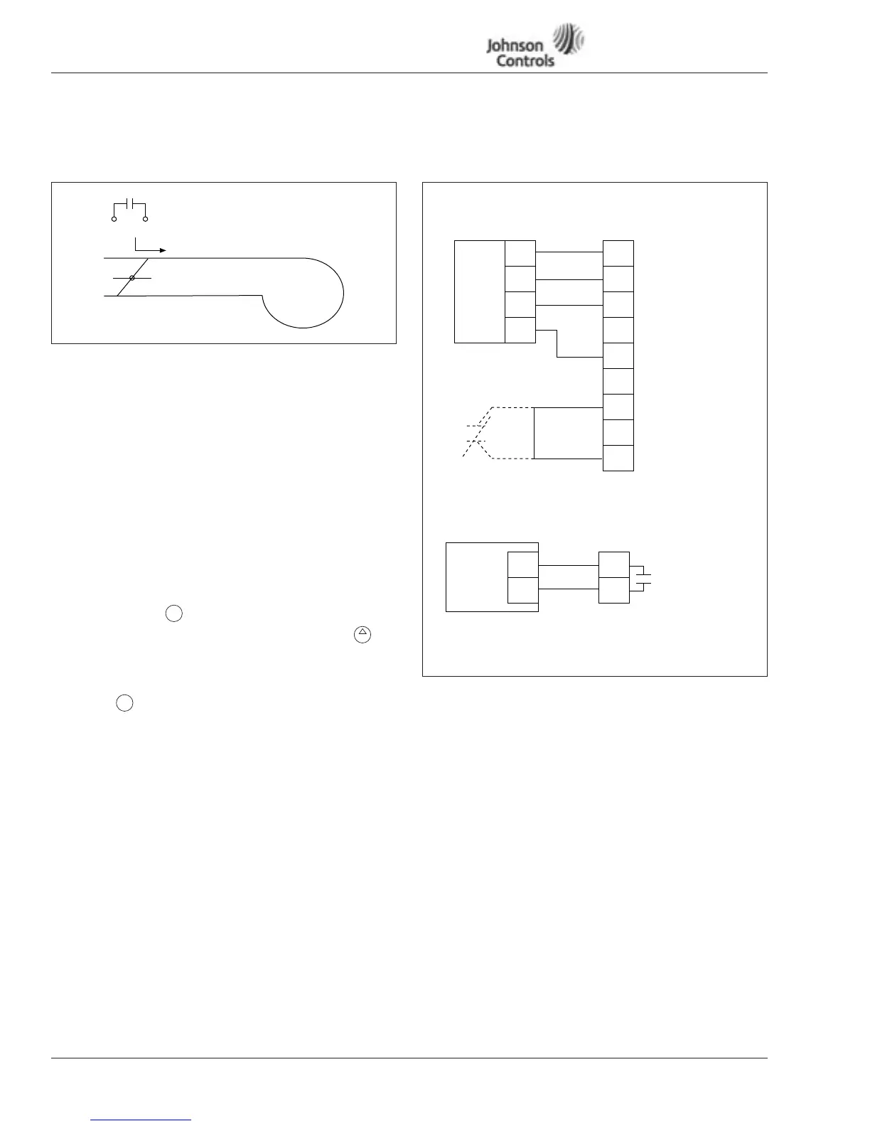
Interlock Damper Start Example Using 4 – 20 mA Control Signal
Figure 11: Interlock Damper Start Example with
Remote 4 – 20 mA Application
Step 1. Wire Load, Line, Digital In/Out per example and verify
voltage and amperage
Step 2. Static check drive SCR, IGBT, DC Bus per Static Check,
Page 20 and 21
Step 3. Start-up Wizard (Remote Input Application)
Step. 4. Set Interlock Start P1.2.1 (Programmable Options)
0. Normal start with Interlock
1. Interlock start from one D1-2….D1-6 (D1-3 Default)
2. Interlock start and timeout supervision. If feedback is
not given in timeout request, the unit will not start.
3. Delay start from Run command
Note: Interlock damper controller works in drive or bypass.
Step 5. Select Hand to test motor rotation
Step 6. To verify proper motor rotation, press start and to
increase speed in Hand mode
Step 7. To run in Remote Auto mode, run Remote Auto –
Hit stop
Hit twice, enter
Send START Signal from Field Controller to start drive.
Figure 12: Programming Example
To Drive Damper
Interlock Terminals
10 12
Fan
HOA
+
HOA
4
5
6
8
10
12
4 – 20 mA
+
-
Run
Field
Controller
Terminals
Factory
Jumper
22
23
Damper Actuator
Input Terminals
A1-2+ Speed
A1-2- Ref
24 Vdc Control
Close Terminal
(6 – 8) to start VFD
D1-1
D1-3 Run Permisive
Damper Interlock
(Default)
24 Vdc Control
Voltage
Closes on Run
(Default)
8 A/24 Vdc
.8 A/125 Vac
.4 A/250 Vac
(D1-3 Default)
OPTA2 Slot B
OPTA9 Slot A
 Loading...


