VSD Series Quick Start Guide
Powered by
Eaton’s Technology
4
For more information visit:
www.johnsoncontrols.com
LIT-1201858
November 2009
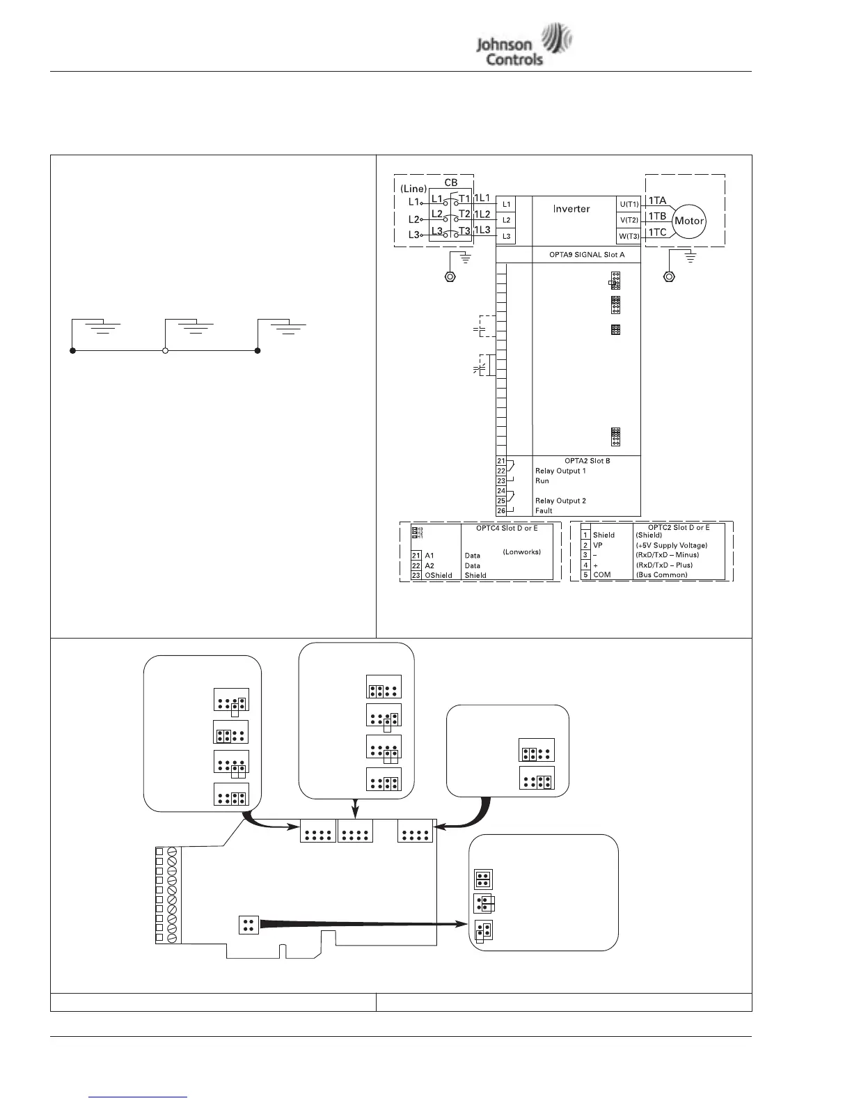
NEMA Type 1/12 Open Drives (1 – 250 HP)
Table 1: Control Wiring Instructions (continued)
Control Wiring
9. Wire control to the OPTA9 Control Board and OPTA2.
Note:
Drive default is programmed for Damper Interlock.
Note:
Option Boards OPTC2 (N2/XT/SA Bus) and OPTC4
(LonWorks) are optional.
Mandatory Ground Wiring
Be sure to pull low impendance ground wiring from
customer power to drive and ground wire from drive
to motor.
I/O Connection
•
Run 110 Vac and 24 Vdc Control wiring in separate
conduit.
•
Communication wire to be shielded.
•
RS-232 Keypad cable less than 20 feet.
Figure 2:
Figure 3: Option Board A9 Location and Settings
Start-Up Wizard
See
Appendix G
.
Utility Drive Motor Ground
(Inside Motor Conduit Box)
Note:
+1DV
Vin+
GND
Lin+
Lin–
24Vout
GND
DIN1
DIN2
DIN3
CMA
24Vout
GND
DIN4
DIN5
DIN6
CMB
Lout+
Lout–
DO1
1
2
3
4
5
6
7
8
9
10
11
12
13
14
15
16
17
18
19
20
Reference Output
I/O Ground
Control Voltage Output
I/O Ground
Start/Stop
External Fault
DIN1-DIN3 Common
Control Voltage Output
I/O Ground
Speed Select 1
Fire Mode
Bypass Overload Fault
DIN4-DIN6 Common
Output Frequency
Analog Output
Digital Output Ready
Analog Input Voltage
(Range 0-10V DC)
X1
X2
X3
A
B
C
D
A
B
C
D
Analog Input Current
(Range 4-20mA)
X6
A
B
C
D
Note: Must pull
dedicated
ground wire
to drive
and motor.
Run Permisive Damper Interlock
Note:
See Figure 3
for Dip X1, X2,
X3, X6 Switch
settings.
Optional Communication Cards can be
supplied with the Drive or as a Field Option.
Optional
CB
Incoming Power
CMB and CMA Internally
Connected and Isolated
from Ground
X1 Jumper Setting
Analog Input 1 (AI1)
X2 Jumper Setting
Analog Input 2 (AI2)
X6 Jumper Setting
Analog Output 1 (A01)
X3 Jumper Setting
CMA and CMB Grounding
0 to 10V*
Voltage Input
-10 to 10V
Voltage Input
0 to 20 mA
Current Input
0 to 10V
(Differential)
Voltage Input
CMB Connected to Ground*
CMA Connected to Ground
CMB Isolated from Ground
CMA Isolated from Ground
* Designates Default Jumper Settings
0 to 20 mA*
Current Input
0 to 10V
Voltage Input
0 to 10V
(Differential)
Voltage Input
-10 to 10V
Voltage Input
0 to 20 mA*
Current Output
0 to 10V
Voltage Output
A
B
C D
A
B
C D
A
B
C D
X1
X3
X2
X6
A
B
CD
A
B
CD
A
B
C D
A
B
CD
A
B
CD
A
B
CD
A
B
C D
A
B
CD
A
B
CD
A
B
CD
 Loading...


