Powered by
Eaton’s Technology
VSD Series Quick Start Guide
LIT-1201858
For more information visit:
www.johnsoncontrols.com
7
November 2009
NEMA Type 1 IntelliPass/IntelliDisconnect Drive
Table 3: Bypass Power Wiring Instructions — NEMA Type 1 (continued)
Motor Wiring
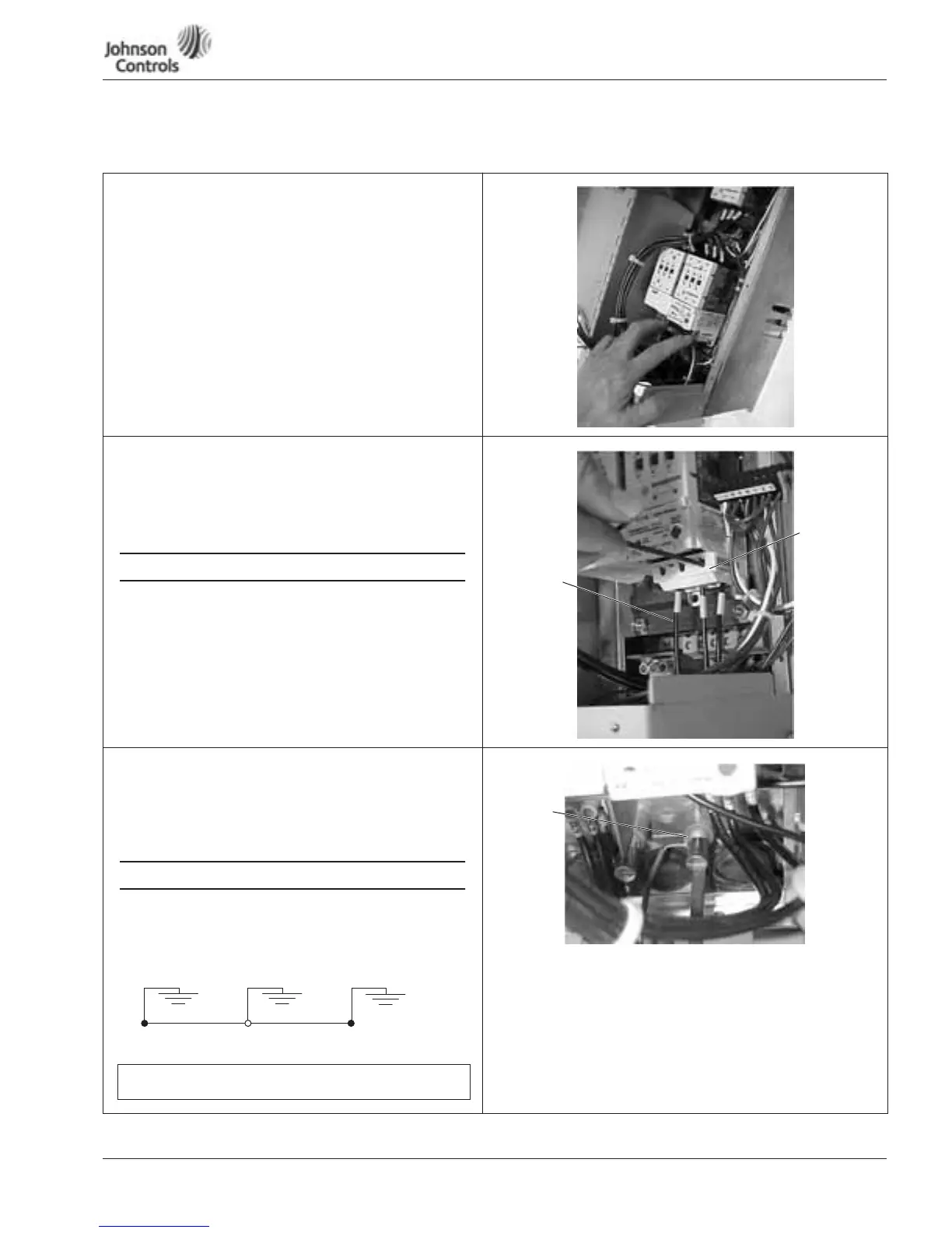
13. Use your first and second fingers and simultaneously
push down to release the two orange retaining clips (one
on each side of the 24V DC motor overload terminal
block).
14. If necessary, use a flat-blade screwdriver to carefully
remove the terminal block in a straight plane to avoid
damaging it.
Motor Wiring
15. Connect the motor leads to the motor overload terminals
labeled 1TA, 1TB and 1TC.
16. Using the appropriate
metric
Allen wrench (2.5 mm, 3 mm
or 4 mm), tighten each overload terminal per the
specifications in the contactor user’s manual.
An SAE allen wrench will damage the terminals,
and the motor overload will need to be replaced
(not covered by warranty).
17. Using the torque wrench, tighten each terminal to the
torque value found in the appropriate user’s manual
supplied with the drive.
18. Reinsert the motor overload terminal block.
Grounding
19. Use a flat-blade screwdriver to connect the motor ground
wire to the ground stud (located at either the top or
bottom of the drive’s enclosure). (Mandatory) Ground
connection main power ground must be connected to
other ground screws.
•
Run motor cables in separate conduit.
•
DO NOT RUN CONTROL WIRES in same conduit
•
Cables sized per NEC.
•
Provide low impedance ground between drive and
motor.
MOTOR WIRING
Motor
Leads
Motor
Overload
Terminals
GROUND WIRING
Utility Drive Motor Ground
(Inside Motor Conduit Box)
IMPORTANT: Improper grounding could result in damage to the
motor and/or drive and could void warranty
Motor
Ground
Stud
 Loading...


