6074816-UIM-A-0421
Johnson Controls Ducted Systems 11
FIELD CONNECTIONS CONTROL WIRING
1. Route low voltage wiring into bottom of control box as shown in Fig-
ure 13, 14, or 15. Make low voltage wiring connections inside the
low voltage box as shown in Figure 16.
2. The complete connection diagram and schematic wiring label is
located on the inside surface of the unit service access panel.
3. Replace the control box cover removed in Step 2 of the Field Con-
nections Power Wiring procedures.
4. All field wiring to be in accordance with national electrical codes
(NEC) or local city codes.
5. Mount the thermostat about 5 ft above the floor, where it is exposed
to normal room air circulation. Do not place it on an outside wall or
where it is exposed to the radiant effect from exposed glass or
appliances, drafts from outside doors or supply air grilles.
6. Route the 24-V control wiring (NEC Class 2) from the outdoor unit
to the indoor unit and thermostat.
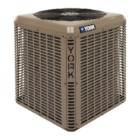
Figure 13: Outdoor Unit Control Box (Single Phase - Smaller Base)
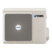
Figure 14: Outdoor Unit Control Box (Single Phase - Larger Base)
5(9(56,%/(+,*+
92/7$*(&21'8,7
3/$7(
*5281'
/8*
67$57
&$3$&,725
&217$&725
581
&$3$&,725
/2:92/7$*(
),(/':,5,1*
/2:
92/7$*(
%2;
67$57
5(/$<
$
+,*+92/7$*(
),(/':,5,1*
2SWLRQDODFFHVVRULHVRQVRPHPRGHOV
67$57
5(/$<
&217$&725
67$57
&$3$&,725
*5281'
/8*
5(9(56,%/(
+,*+92/7$*(
&21'8,73/$7(
581
&$3$&,725
/2:
92/7$*(
%2;
$
/2:92/7$*(
),(/':,5,1*
+,*+92/7$*(
),(/':,5,1*
2SWLRQDODFFHVVRULHVRQVRPHPRGHOV
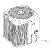
Figure 15: Outdoor Unit Control Box (Three Phase)
NOTICE
A Start Assist Kit is available and recommended for long lineset appli-
cations or in areas of known low voltage problems. The kit may be
required when a TXV is used (refer to the Tabular Data Sheet to
determine if applicable).
NOTICE
To eliminate erratic operation, seal the hole in the wall at the thermo-
stat with permagum or equivalent to prevent air drafts affecting the
operation of in the thermostat.
5(9(56,%/(+,*+
92/7$*(&21'8,7
3/$7(
*5281'
/8*
&217$&725
)$1
&$3$&,725
/2:92/7$*(
),(/':,5,1*
/2:
92/7$*(
%2;
$
+,*+92/7$*(
),(/':,5,1*
2SWLRQDODFFHVVRULHVRQVRPHPRGHOV