6074816-UIM-A-0421
8 Johnson Controls Ducted Systems
SECTION V: EVACUATION
It is necessary to evacuate the system to 500 microns or less. If a leak
is suspected, leak test with dry nitrogen to locate the leak. Repair the
leak and test again.
To verify that the system has no leaks, close the valve to the vacuum
pump suction to isolate the pump and hold the system under vacuum.
Watch the micron gauge for a few minutes. If the micron gauge indi-
cates a steady and continuous rise, it’s an indication of a leak. If the
gauge shows a rise, then levels off after a few minutes and remains
fairly constant, it’s an indication that the system is leak free but still con-
tains moisture and may require further evacuation if the reading is
above 500 microns.
SECTION VI: SYSTEM CHARGE
To ensure that your unit performs at the published levels, it is important
that the indoor airflow is determined and refrigerant charge is added
accordingly.
MEASURING INDOOR AIRFLOW
To determine rated airflow for a specific match, consult the technical lit-
erature at
www.simplygettingthejobdone.com. When attempting to
match this airflow, select the lowest possible speed tap, measure the
actual airflow, and adjust as necessary.
To measure actual airflow, it is not an acceptable method to just
check the jumper pin setting tables and to assume 0.5 in. W.C.
total external static pressure.
To determine indoor airflow, first measure the static pressure with a
manometer between the filter and blower. On a single-piece air handler,
take a second reading after the coil. On a furnace or modular air han-
dler, take the second reading after the heat exchanger but before the
indoor coil. Add the negative return static to the positive supply static to
determine the system total static pressure. Treat the negative return
static as a positive pressure (even though it is a negative reading). If
there is static pressure on the blower return (-0.1), add it to a supply
static (0.4) which equals a (0.5) total system static pressure. Compare
this value to the table for the indoor unit's static pressure against CFM
or to a curve chart.
SYSTEM CHARGING
The factory charge in the outdoor unit includes enough charge for the
unit, a 15 ft (4.6 m) line set, and the smallest indoor coil match-up.
Some indoor coil matches may require additional charge. Refer to the
Tabular Data Sheet for charge requirements.
The total system charge must be permanently stamped on the unit data
plate.
Total system charge is determined as follows:
1. Determine the base charge shipped in the outdoor unit by referring
to the Tabular Data Sheet included with the outdoor unit.
2. Determine the charge adder for the matched indoor unit by referring
to the Tabular Data Sheet.
3. If the line set length is greater than 15 ft (4.6 m), calculate the
charge adder for actual line set length by referring to the Tabular
Data Sheet.
4. Once the charge adders for the matched indoor unit and for the line
set have been weighed in, verify the system operation against the
temperatures and pressures in the charging chart for the outdoor
unit. Refer to the Charging Charts on the outdoor unit or in the Ser-
vice Application Data on
www.simplygettingthejobdone.com. Follow
the subcool or the superheat charging procedure in this section
according to the type of indoor metering device in the system, and
allow 10 min after each charge adjustment for the system operation
to stabilize. Record the charge adjustment made to match the
charging chart.
5. Verify that total system charge = base charge (as shipped) + charge
adder for matched indoor unit + charge adder for actual line set
length + charge adjustments to match the charging chart.
6. Permanently stamp the unit data plate with the total system charge
as defined in these instructions.
Use this method whenever additional refrigerant is required for the sys-
tem charge.
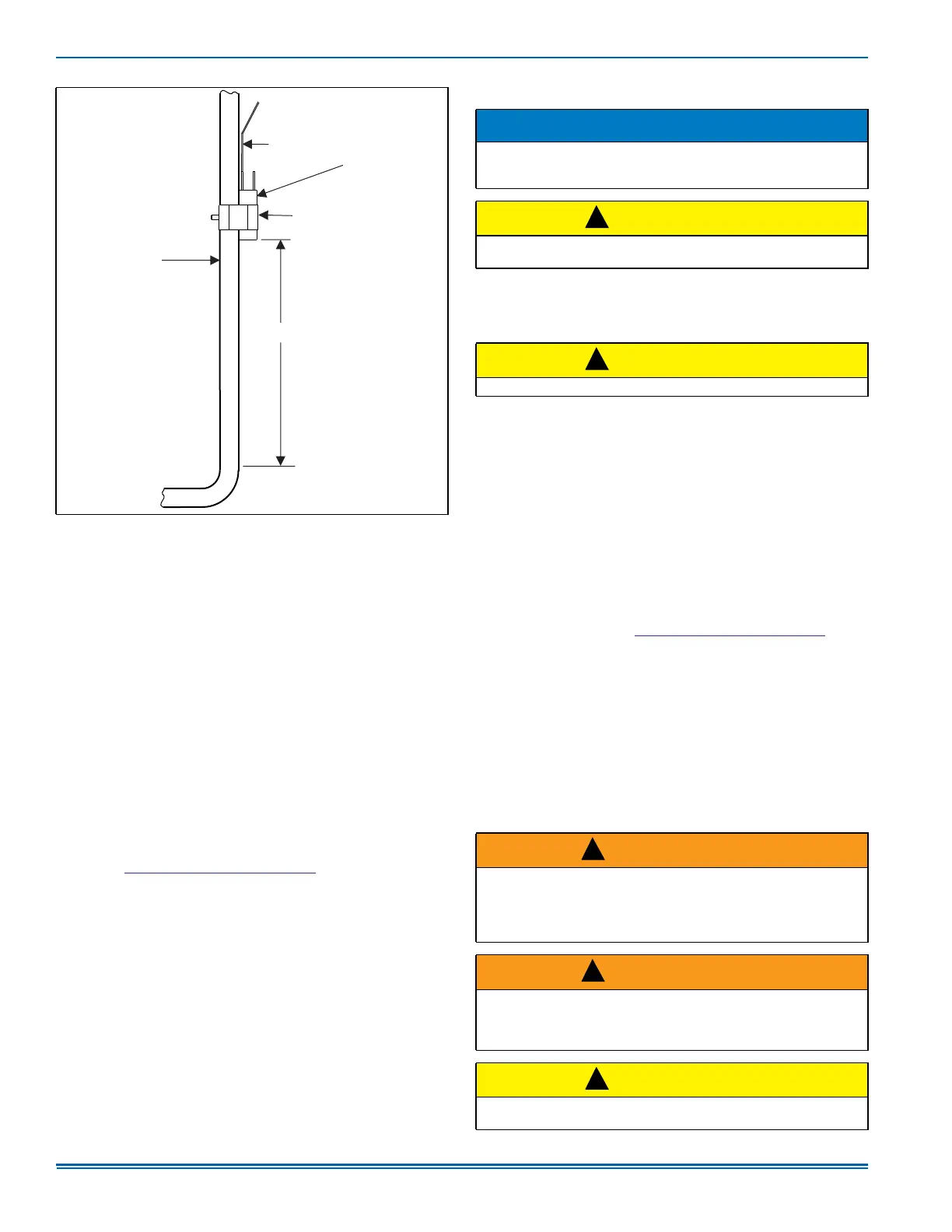
Figure 11: Vertical Temperature Bulb Orientation
9$325/,1(
2)/,1(6(7
$
&/$03
7;9
7(03(5$785(
%8/%
7$,/(1'83
´FP(QVXUHEXOELV
DWOHDVW´IURPDQ\EHQG
127(
(QVXUHEXOELVRQRSSRVLWH
VLGHRIWXELQJEHQGSODQH
NOTICE
For cold weather charging of the system at temperatures of 55°F or
below, see the Optional Cold Weather Charging procedures near the
end of SECTION VI: SYSTEM CHARGE.
CAUTION
R-410A refrigerant cylinders are rose colored. Always charge the
system slowly with liquid R-410 refrigerant.
CAUTION
Do not leave the system open to the atmosphere.
WARNING
Do not attempt to pump the total system charge into the outdoor unit
for maintenance or service. This may cause damage to the compres-
sor or other components. Recover and weigh the system charge into
an appropriate recovery cylinder for any instances requiring evacua-
tion.
WARNING
Do not attempt to pump more than the factory charge and an addi-
tional 15-ft line charge into a tube and fin outdoor unit for mainte-
nance or service. This can cause damage to the compressor or other
components.
CAUTION
Refrigerant charging must only be carried out by a qualified air condi-
tioning contractor.
!
!
!
!
!