6074816-UIM-A-0421
2 Johnson Controls Ducted Systems
INSPECTION
As soon as a unit is received, you must inspect it for possible damage
during transit. If damage is evident, you must note the extent of the
damage on the carrier’s delivery receipt. A separate request for inspec-
tion by the carrier’s agent must be made in writing. See Local Distribu-
tor for more information.
Requirements for installing or servicing R-410A equipment
• Gauge sets, hoses, refrigerant containers, and the recovery sys-
tem must be designed to handle the POE type oils and the higher
pressures of R-410A.
• Manifold sets must be high side and low side with low side retard.
• All hoses must have a 700-psig service pressure rating.
• Leak detectors must be designed to detect HFC refrigerant.
• Recovery equipment (including refrigerant recovery containers)
must be specifically designed to handle R-410A.
• Do not use an R-22 TXV.
LIMITATIONS
You must install the unit in accordance with all national, state, and local
safety codes, and the following limitations:
1. Limitations for the indoor unit, coil, and appropriate accessories
must also be observed.
2. The outdoor unit must not be installed with any duct work in the air
stream. The outdoor fan is the propeller type and is not designed to
operate against any additional external static pressure.
3. The maximum and minimum conditions for operation must be
observed to ensure a system that gives maximum performance with
minimum service.
4. The unit must not be operated at outdoor temperatures below 55°F
without an approved low ambient operation accessory kit installed.
5. The maximum allowable line length for this product is 80 ft. To
install more than the maximum allowable line length, consult the
Piping Application Guide (P/N 247077).
SECTION III: UNIT INSTALLATION
LOCATION
Before starting the installation, select and check the suitability of the
location for both the indoor and outdoor unit. Observe all limitations and
clearance requirements.
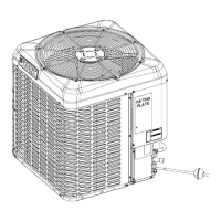
The outdoor unit must have sufficient clearance for air entrance to the
condenser coil, air discharge, and service access. See Figures 1 and 2.
If the unit is to be installed on a hot sun-exposed roof or a paved ground
area that is seasonally hot, the unit must be raised sufficiently above
the roof or ground to avoid taking the accumulated layer of hot air into
the outdoor unit.
If the system is being installed during seasonally cold weather of 55°F
or below, the preferred method is to weigh in the charge. For charging
or checking the system charge at 55°F or below, see the Optional Cold
Weather Charging procedures near the end of Section VI: System
Charge. There is an Optional Cold Weather Charging accessory kit to
prevent the outdoor unit from taking in cold air below 55°F. The kit part
number can be found in the list of accessory kits at
www.simplygettingthejobdone.com.
Provide adequate structural support for the unit.
ADD-ON REPLACEMENT OR RETROFIT
When using this unit as a replacement for an R-410A unit, you must
replace the outdoor unit, indoor coil, and metering device. The following
steps must be performed in order to insure correct system operation
and performance. Line set change out is also recommended.
1. Change out the indoor coil to an approved R-410A coil and con-
densing unit combination with the appropriate metering device.
2. Change out the line set when replacing an R-22 unit with an R410-
A unit to reduce cross-contamination of oils and refrigerants. If
change-out of the line set is not practical, then the following precau-
tions must be taken:
• Inspect the line set for kinks, sharp bends, or other restrictions,
and for corrosion.
• Determine if there are any low spots which might be serving as oil
traps.
• Flush the line set with a commercially available flush kit to
remove as much of the existing oil and contaminants as possible.
• Install a suction line filter-drier to trap any remaining contami-
nants and remove after 50 h of operation.
If replacing the outdoor unit due to a compressor burnout, then installa-
tion of a 100% activated alumina suction-line filter-drier in the suction-
line is required, in addition to the factory installed liquid-line drier. Install
the suction-line filter-drier by completing the following steps:
1. Operate the system for 10 h and monitor the suction drier pressure
drop. If the pressure drop exceeds 3 psig, replace both the suction-
line and liquid-line driers.
2. After a total of 10 h run time where the suction-line pressure drop
has not exceeded 3 psig, replace the liquid-line drier and remove
the suction-line drier. Never leave a suction-line drier in the system
longer than 50 h of run time.
Table 1: Application Limitations
Ambient Air
Temperature on
Outdoor Coil (°F)
Air Temperature
on
Indoor Coil (°F)
MODEL
Minimum
DB
Maximum
DB
Minimum
WB
Maximum
WB
YCD/TC3/RAC13L 55 115 57 72
YCS/YFE/YCE/TW4/
TF4/TC4/RAC14L/
RAW14L/RAC14F/
YCG/TC7/CC7/RAC17L
55 125 57 72
NOTICE
For multiple unit installations, units must be spaced a minimum of
24 in. (61 cm) apart (coil face to coil face).