6074816-UIM-A-0421
6 Johnson Controls Ducted Systems
12. Release the refrigerant charge into the system. Open both the liq-
uid and vapor valves by removing the plunger cap and with an hex
wrench, back out counterclockwise until the valve stem just touches
the chamfered retaining wall. If the service valve is a ball valve, use
a adjustable wrench to turn the valve stem 1/4 turn counterclock-
wise to open. Do not overturn or the valve stem may break or
become damaged. See Precautions during brazing service valve.
13. Replace the plunger cap finger tight, then tighten an additional 1/12
turn (1/2 hex flat). The cap must be replaced to prevent leaks.
See System charge for checking and recording system charge.
SECTION IV: COIL METERING DEVICES
A piston or a TXV is to be installed in the field. There is an installation
manual that comes with the TXV kit. Install the piston or TXV kit before
installing the coil and brazing the line set. Until brazing is completed
and cooled, the TXV sensing bulb must not be installed.
Refer to the outdoor technical guide for outdoor units for the required
piston or TXV on the indoor coil. The piston and the Schrader core are
supplied with the outdoor unit. When using the piston instead of the
TXV, the Schrader core is installed in the suction-line equalizer connec-
tion port and is capped with the supplied plastic cap. The Schrader core
must not be installed if the TXV is installed, because the TXV equalizer
line attaches to the equalizer connection port.
PISTON INSTALLATION
Install Schrader Valve Core and
Piston as follows:
1. After the holding charge is completely discharged, remove the
black plastic cap from the equalizer connection port on the vertical
part of the vapor line.
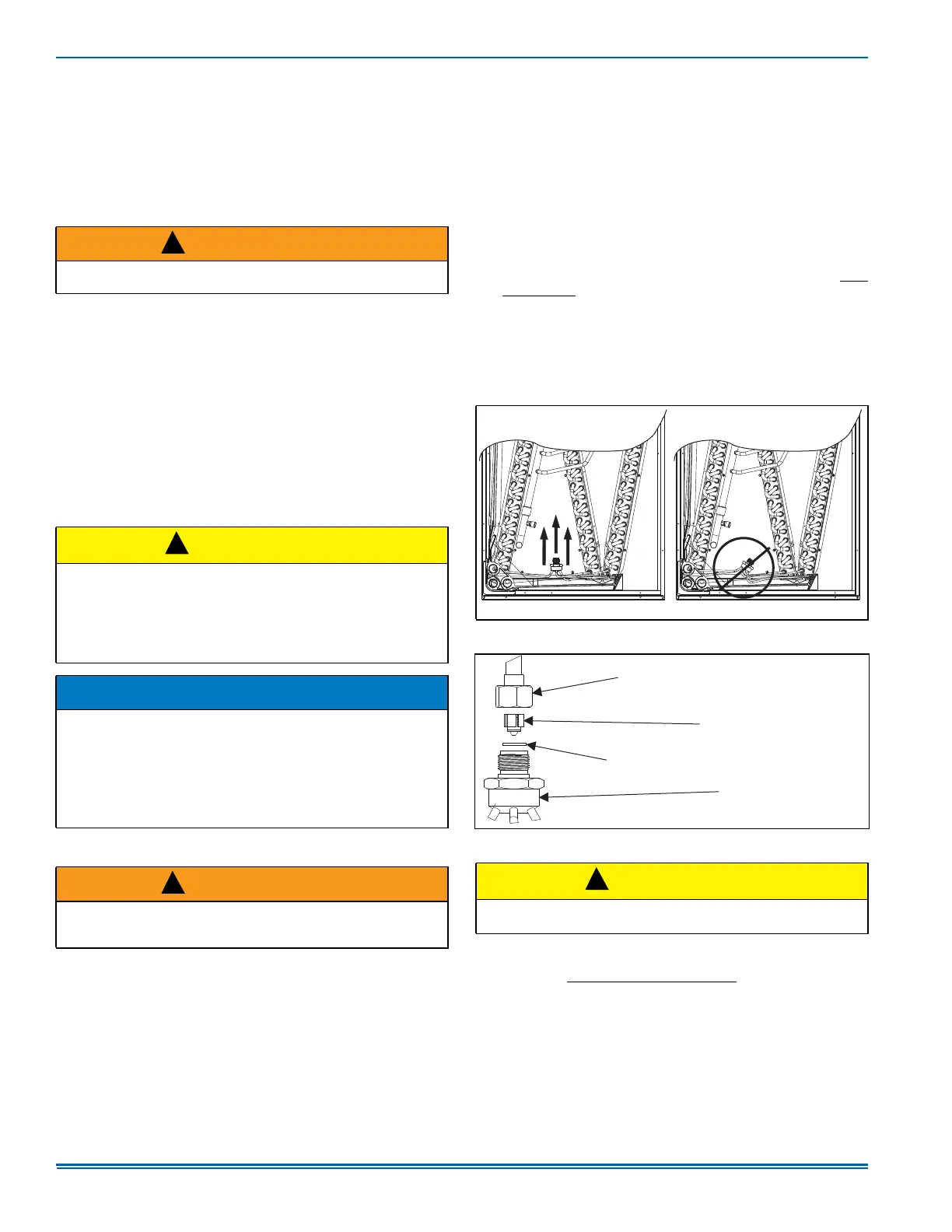
2. Adjust the distributor position to allow the preformed liquid line
assembly to correctly line up with the hole in the tubing access
panel. Raise the distributor body approximately 2 in. toward the top
of the coil or what would be the top of the coil if the coil was in the
upflow position. See Figure 6 and adjust as necessary.
3. Install the Schrader valve core supplied with the outdoor unit into
the equalizer fitting connection port using a valve core tool.
4. Loosen and remove the liquid line connection nut and the sealing
disc from the distributor assembly. Note that the fitting has right-
hand threads.
5. Slide the nut over the liquid line to be installed and discard the seal
disc.
6. Install the required size piston into the distributor. Refer to the Tabu-
lar Data Sheet for the specific piston size and indoor coil match up.
7. Verify that the PTFE washer is still in place in the distributor open-
ing. See Figure 7.
8. After installing the piston, install the liquid line to the top of the pis-
ton or distributor assembly. Hand tighten and turn an additional 1/4
turn to seal. Do not over-tighten the fittings.
9. Replace the black plastic cap on the unused equalizer fitting con-
nection port.
10. After installing the line set, leak test the system.
WARNING
Never attempt to repair any brazed connections while the system is
under pressure. Personal injury could result.
CAUTION
COIL UNDER PRESSURE.
Verify that pressure has been released by depressing the Schrader
valve core.
The coil requires a metering device to be added.
Refer to the outdoor unit documentation for the correct TXV or piston
to be used.
NOTICE
To prevent moisture and contaminates from entering the system, the
coil must not be open to atmosphere for extended periods of time. If
the coil cannot be brazed into the refrigeration system during a rou-
tine installation period, the ends must be temporarily closed or
plugged. For a short term delay, use masking tape over the ends of
the copper tubing to close the tube from the air. For a longer term
delay, use plugs or caps. There is no need to purge the coil if this pro-
cedure is followed.
WARNING
Failure to install the Schrader Valve Core in the vapor line equalizer
connection port for piston applications could result in total refrigerant
loss of the system.
!
!
!
Figure 6: Recommended Distributor Adjustment
Figure 7: Piston Installation
CAUTION
Do not over-tighten. Do not use slip joint pliers. This distorts the alu-
minum distributor and the brass fitting (potentially causing leaks).
A0305-002
DISTRIBUTOR
PISTON
LIQUID LINE SWIVEL COUPLING
(This ¿WWLQJLVDULJKWKDQGHGWKUHDG
TXUQFRXQWHUFORFNZLVHWRUHPRYH
PTFE WASHER
!