6074816-UIM-A-0421
Johnson Controls Ducted Systems 7
THERMOSTATIC EXPANSION VALVE (TXV)
INSTALLATION
The following are basic steps for installation. For detailed instructions,
refer to the TXV kit Installation Manual. Install the TXV as follows:
1. Relieve the holding charge by depressing the Schrader core on the
suction manifold stub out.
2. After the holding charge is completely discharged, loosen and
remove the Schrader core.
3. Place a backup wrench on the distributor, then loosen and remove
the brass distributor nut. Retain the brass nut for use on the liquid
line. Keep the PTFE washer in place and discard the clear disk.
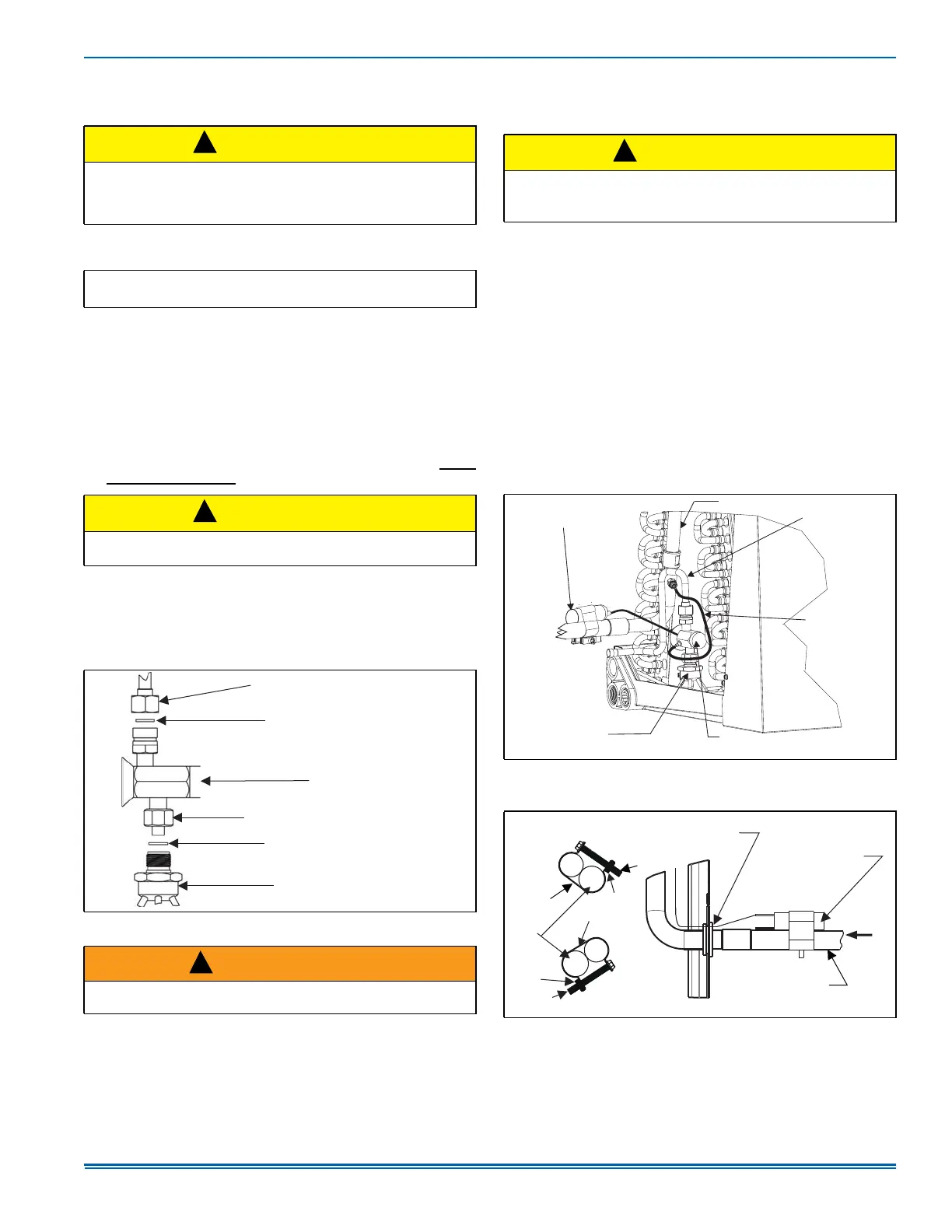
4. Install the thermal expansion valve to the distributor assembly with
the supplied fittings. Ensure the PTFE washer is seated in the dis-
tributor. Hand tighten and turn an additional 1/4 turn to seal.
Do not
over-tighten the fittings. See Figure 8.
5. Slide the nut removed in Step 3 over the supplied liquid line. Place
the supplied PTFE washer from the TXV kit on the TXV, and install
the liquid line to the top of the thermal expansion valve. Adjust the
assembly so the liquid line aligns with the hole in the access panel.
See Figure 9. Hand tighten the liquid line and apply an additional
1/4 turn to seal.
6. Install the TXV equalizer line onto the vapor line by hand tightening
the 1/4-in. SAE coupling nut to the equalizer fitting and apply an
additional 1/3 turn to seal. See Figures 9, 10, and 11.
7. Pass the temperature sensing bulb tube for the TXV through the
tube opening in the split grommet of the access panel.
8. Install the TXV bulb to the vapor line near the cabinet, using the
bulb clamps furnished with the TXV assembly. Ensure the bulb
makes maximum contact. See Figures 9, 10 and 11, and do the fol-
lowing:
a. If possible, install the temperature bulb on a horizontal run of the
vapor line. Ensure that the bulb is installed at a 10 o’clock or 2
o’clock position. See Figure 10.
b. If bulb installation is made on a vertical run, ensure that the bulb
is a minimum of 8 in. (20.3 cm) away from the elbow coming out
of the coil. Position the bulb with the tail of the bulb at the top, so
that the bulb acts as a reservoir. See Figure 11.
c. Insulate the bulb using the thermal insulation provided to protect
it from the effect of the surrounding ambient temperature. Cover
completely to insulate.
9. After the line set is installed, leak test the system.
CAUTION
Outdoor unit model numbers ending with an H have a factory installed
hard start kit which is required when a TXV kit is installed. Outdoor
unit model numbers with no H ending do not require a hard start kit
unless local regulations dictate it.
IMPORTANT: Refer to the Technical Guide for the unit to determine
the proper TXV to be used on this product.
CAUTION
Do not over-tighten. Do not use slip joint pliers. This distorts the alu-
minum distributor and the brass fitting (potentially causing leaks).
Figure 8: TXV Installation
WARNING
The Schrader valve core must not be installed with TXV installation.
Poor system performance or system failure could result.
!
!
TXV / DISTRIBUTOR COUPLING
LIQUID LINE / TXV COUPLING
PTFE WASHER
TXV
PTFE WASHER
DISTRIBUTOR
A0281-003
!
CAUTION
In all cases, mount the TXV temperature sensing bulb after the vapor
line is brazed and sufficiently cooled.
Failure to use a suction-line split grommet may result in TXV failure.
Figure 9: TXV Bulb and Equalizer line Installations
Figure 10: Correct Bulb Location
!
TXV BULB
(Wrap with
insulation.)
VAPOR LINE
LIQUID LINE
TVX
EQUALIZER
LINE
THERMAL EXPANSION
VALVE
TXV
DISTRIBUTOR
BODY
A0279-002
TXV BULB
(Cover completely
with insulation.)
VAPOR LINE
OF LINE SET
A0269-002
CLAMP
A
DETAIL A
TXV SENSING BULB
(Pass through split hole
in grommet.)
VAPOR
LINE
NUT
NUT
Bulb at
10 o’clock
position.
Bulb at
2 o’clock
position.
SCREW
SCREW
CLAMP