13
GB
Micro-switches SW1 allow the configuration
of the following parameters:
- Pin 1: Lock keyboard. In
OFF the keyboard
is not locked. In ON the keyboard is locked
and the locked keyboard symbol ( ) is
displayed. The buttons that remain ac-
tive are: , and (outdoor
temperature reading).
- Pin 2:
AUTO PROG mode activated.
Defines whether the automatic air con-
ditioning mode with time schedule pro-
gramming (time schedule profiles) can be
activated. OFF indicates the AUTO PROG
mode is deactivated, and ON indicates
the AUTO PROG mode can be selec-
ted.
- Pin 3: O/B signal: Set to OFF, heat is
generated when the O/B (24 VAC) signal is
active, and cool when inactive. Set to ON,
cool is generated when the O/B (24 VAC)
signal is active, and heat when inacti-
ve.
- Pin 4: 2 minutes/4 minutes. Defines the
time between the end of one phase and
when it can be active again. OFF indicates
2 minutes, and ON, 4 minutes.
- Pin 5: Multi-stage. Defines single-stage
(one stage can be activated only) or multi-
stage (more than one can be activated).
OFF indicates single-stage and ON, multi-
stage.
- Pin 6: Single-speed fan. Defines whether
the fan can operate at one or three speeds.
OFF indicates 3 speeds and ON, 1 speed.
In single-speed, the wind icons are not
displayed.
Alarms
The alarm codes are displayed at the bot-
tom left of the screen, overlapping hour and
minutes.
The alarm codes are as follows:
- 0-90, machine error codes.
- 91, temperature origin selected is
invalid.
- 92, indoor temperature sensor not cali-
brated.
- 93, communication alarm.
- 94, alarm with terminal "AL" connected.
- 95-99, digital probe not detected.
- When an alarm is generated, the wren-
ch symbol is displayed. If the error is
machine or communication, this symbol
flashes; if not, it remains static.
- Filters. If the dirty filters symbol is dis-
played flashing, the filters need to be
changed.
- Dead battery. The dead battery symbol
indicates the batteries are dead, and
these should be changed. System con-
figuration is not lost when changing the
batteries. Only day and time are lost.
Table of lockouts (Red LED)
outdoors.
- Where operation can be affected by steam
or water pipes, or hot air chimneys in
adjacent areas or any other unheated/un-
cooled area behind the thermostat.
- Where operation can be affected by the
supply air of any adjacent unit.
- Near sources of electrical interference,
such as arching relay contacts.
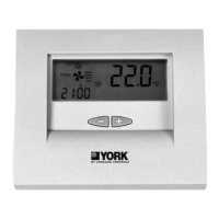
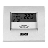
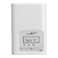
Basic elements
This thermostat comprises three parts:
- Hinged front cover.
- Front panel. This element contains the
operating and control keys, as well as the
printed circuit. Fastened to the base by
means of a plastic tab.
- The base. This box allows fastening the
thermostat to the wall, and contains the
electrical connecting strips.
Installation instructions
It is recommended that the installation be
carried out by a qualified personal.
Location
To assure adequate operation, this thermo-
stat should be installed on an indoor wall, in
a frequently occupied area of the building.
Furthermore, it should be at at least 50 cms.
from any outside wall, and at approximately
1.5 m. above floor level, in an area with freely
circulating air at average temperature. The
following locations should be avoided:
- Behind doors or in corners where freely
circulating air is unavailable.
- Where direct sunlight or radiant heat gen-
erated by other appliances may alter the
control operation.
- On an outside wall.
- Next to or in line with air conditioning dis-
charge grids, stairwells or doors leading
Code Designation
11 / 21 / 31
Compressor discharge temperature surpased or
short circuited probe
12 / 22 / 32
High Pressure switch, outdoor fan overload or
compressor motor protection module
13 / 23 / 33 Low Pressure switch
14 Indoor fan thermal switch
15 / 25 / 35
Repeated start-ups in cool, or suction temperature
< -25°C
16 Liquid temperature < -30°C
41 Gas 1 or electrical heater 1
42 Gas 2 or electrical heater 2
43 Electrical heater 3
44 Electrical heater 4
45 Economizer or hot water coil
46
Smoke detector, fire thermostat or air discharge
temperature probe (rooftop only)
91 Selected probe not valid or short circuited probe
92 Thermostat internal probe not calibrate
93 No communication between the thermostat
94 Failure with terminal "AL" connected
95 Digital probe S5 not detected
96 Digital probe S6 not detected
97 Digital probe S7 not detected
98 Digital probe S8 not detected
99
Outdoor digital probe not detected