JOHNSON CONTROLS
104
FORM 150.62-NM6 (103)
SYSTEM LEAD/LAG
Lead/lag between systems may be selected to help
equalize average run hours between systems on chill-
ers with 2 refrigerant systems. This may be programmed
under the OPTIONS key. Auto lead/lag allows automatic
lead/lag of the two systems based on average run hours
of the compressors in each system. Manual lead/lag
selects specically the sequence in which the micro
starts systems.
COMPRESSOR LEAD/LAG
The compressors within a system rotate starts in se-
quence 1, 2 or 1, 2, 3 with wraparound. The longest-off
compressor in a system will start rst, and the longest-
running compressor in a system will turn off rst. When
unloading, the system with the most compressors on,
unloads rst. The lag system will shut down a com-
pressor rst when equal numbers of compressors are
operating in each system. The micro will not attempt to
equalize run time of compressors in a system.
Once the second system has started a compressor, the
micro will attempt to equally load each system. Once this
occurs, loading will alternate between systems.
If Soft Start is enabled on European models with this
option, compressor lead/lag will function as outlined in
Option 12 under the Options key.
ANTI-RECYCLE TIMER
The programmable anti-recycle timer assures that sys-
tems do not cycle. This timer is programmable under the
PROGRAM key between 300 - 600 seconds. Whenever
possible, to reduce cycling and motor heating, the anti-
recycle timer should be adjusted to 600 seconds. The
programmable anti-recycle timer starts the timer when
the rst compressor in a system starts. The timer begins
to count down. If all of the compressors in a circuit cycle
off, a compressor within the circuit will not be permitted to
start until the anti-recycle timer has timed out. If the lead
system has run for less than 5 minutes, 3 times in a row,
the anti-recycle timer will be extended to 10 minutes.
ANTI-COINCIDENCE TIMER
This timer is not present on single-system units. Two
timing controls are present in software to assure com-
pressors within a circuit or between systems, do not start
simultaneously. The anti-coincidence timer assures there
is at least a one minute delay between system starts on
2-circuit systems. This timer is NOT programmable. The
load timers further assure that there is a minimum time
between compressor starts within a system.
EVAPORATOR PUMP CONTROL
The evaporator pump dry contacts (CTB2 – terminals
23 - 24) are energized when any of the following con-
ditions are true:
Unit Controls
Notes:
1. Step 1 is Hot Gas Bypass and is skipped when loading occurs. Hot Gas Bypass operation is inhibited during Pumpdown.
2. Step 3 is skipped when loading occurs.
3. Step 4 is skipped when unloading occurs.
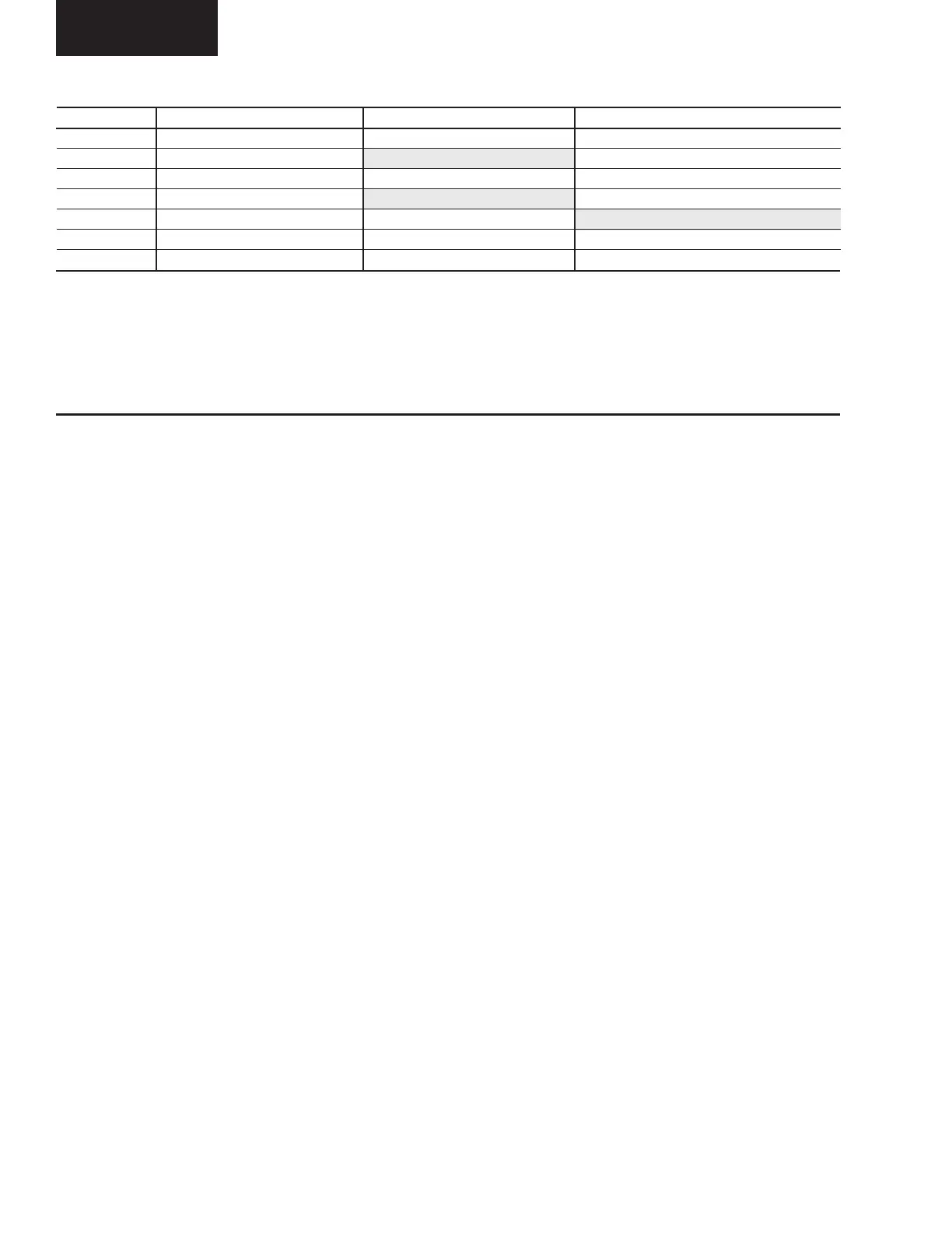
TABLE 26 – RETURN CHILLED LIQUID CONTROL FOR 4 COMPRESSORS (6 STEPS)
*STEP COMPRESSOR COMPRESSOR ON POINT COMPRESSOR OFF POINT
0 0 SETPOINT SETPOINT
1 1 W/HGB SP + CR/8 (Note 1) SETPOINT
2 1 NO HGB SP + CR/4 SP + CR/8
3 2 SP + 2*CR/4 (Note 2) SP + CR/4
4 2 SP + 2*CR/4 SP + CR/4 (Note 3)
5 3 SP + 3*CR/4 SP + 2*CR/4
6 4 SP + CR SP + 3*CR/4
* STEP can be viewed using the OPER DATA key and scrolling to COOLING DEMAND.

 Loading...


