JOHNSON CONTROLS
129
FORM 150.62-NM6 (103)
RECEIVED DATA (CONTROL DATA)
The Middle Market receives 8 data values from the
ISN. The rst 4 are analog values and the last 4 are
digital values. These 8 data values are used as control
parameters when in REMOTE mode. When the unit is
in LOCAL mode, these 8 values are ignored. If the unit
receives no valid ISN transmission for 5 minutes it will
revert back to all local control values. Table 41 lists the
5 control parameters. These values are found under
feature 54 on the ISN.
TRANSMITTED DATA
After receiving a valid transmission from the ISN, the unit
will transmit either operational data or history buffer data
depending on the “History Buffer Request” on ISN PAGE
10. Data must be transmitted for every ISN page under
feature 54. If there is no value to be sent to a particular
page, a zero will be sent. Tables 42 - 43 show the data
values and page listings for this unit.
ISN CONTROL
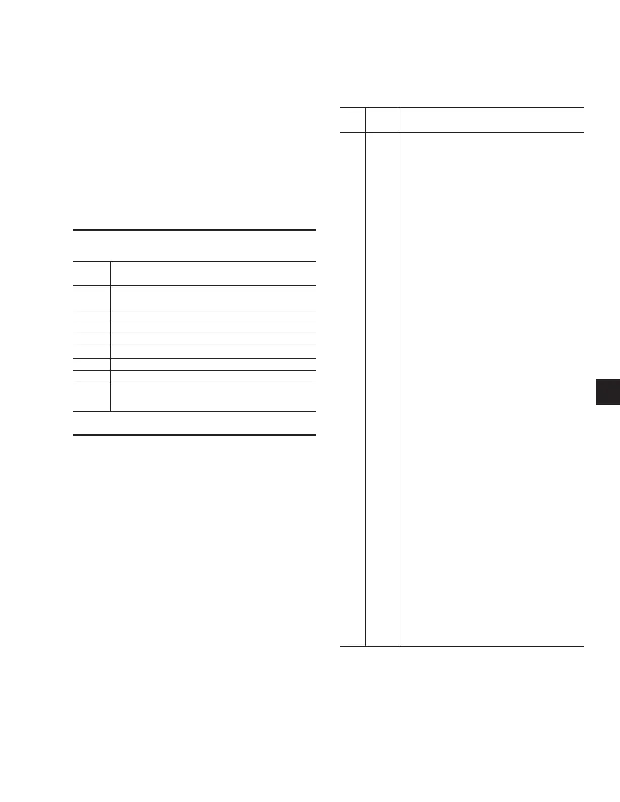
TABLE 42 – ISN TRANSMITTED DATA
ISN
TYPE DATA
PG.
P11 Analog Leaving Chilled Liquid Temp
P12 Analog Return Chilled Liquid temp
P13 Analog –
P14 Analog –
P15 Analog SYS 1 Suction Temp (EEV Only)
P16 Analog Ambient Air Temperature
P17 Analog SYS 1 Suction Superheat (EEV Only)
P18 Analog SYS 1 Run Time (seconds)
P19 Analog SYS 1 Suction Pressure
P20 Analog SYS 1 Discharge Pressure
P21 Analog SYS 1 Cooler Inlet
Refrigerant Temp (R-407c Only)
P22 Analog –
P23 Analog SYS 1 EEV Output % (EEV Only)
P24 Analog SYS 1 Anti-Recycle Timer
P25 Analog Anti-Coincidence Timer
P26 Analog SYS 2 Suction Temp. (EEV Only)
P27 Analog SYS 2 Run Time (seconds)
P28 Analog SYS 2 Suction Pressure
P29 Analog SYS 2 Discharge Pressure
P30 Analog SYS 2 Cooler Inlet
Refrigerant Temp (R-407c Only)
P31 Analog –
P32 Analog SYS 2 Suction Superheat (EEV Only)
P33 Analog SYS 2 Anti-Recycle Timer
P34 Analog SYS 2 EEV Output % (EEV Only)
P35 Analog Number of Compressors
P36 Digital SYS 1 Alarm
P37 Digital SYS 2 Alarm
P38 Digital Evaporator Heater Status
P39 Digital Evaporator Pump Status
P40 Digital SYS 1 Comp 1 Run
P41 Digital SYS 2 Comp 1 Run
P42 Digital SYS 1 Liquid Line Solenoid Valve or
EEV Pilot Solenoid
P43 Digital SYS 1 Hot Gas Bypass Valve
P44 Digital SYS 1 Comp 2 Run
P45 Digital SYS 2 Comp 2 Run
P46 Digital SYS 2 Liquid Line Solenoid Valve
or EEV Pilot Solenoid
P47 Digital Lead System (0=SYS 1, 1=SYS 2)
P48 Digital SYS 1 Comp 3 Run
3
ISN CONTROL DATA
PAGE
P03 SETPOINT
99 = AUTO
P04 LOAD LIMIT STAGE (0,1, 2)
P05 –
P06 –
P07 START/STOP COMMAND (0 = STOP, 1 = RUN)
P08 —
P09 —
P10 HISTORY BUFFER REQUEST
(0 = CURRENT DATA, 1 = LAST HISTORY DATA)
TABLE 41 – ISN RECEIVED DATA

 Loading...


