JOHNSON CONTROLS
103
FORM 150.62-NM6 (103)
2
As an example of compressor staging (refer to Table 34),
a chiller with six compressors using a Cooling Setpoint
programmed for 45°F (7.20°C) and a Range Setpoint
of 10°F (5.56°C). Using the formulas in Table 25, the
control range will be split up into six (seven including
hot gas) segments, with the Control Range determining
the separation between segments. Note also that the
Cooling Setpoint is the point at which all compressors
are off, and Cooling Setpoint plus Range is the point
all compressors are on. Specically, if the return water
temperature is 55°F (12.8°C), then all compressors
will be on, providing full capacity. At nominal gpm, this
would provide approximately 45°F (7.2°C) leaving water
temperature out of the evaporator.
If the return water temperature drops to 53.4°F (11.9°C),
one compressor would cycle off leaving ve compres-
sors running. The compressors would continue to cycle
off approximately every 1.7°F (.94°C), with the exception
of hot gas bypass. Notice that the hot gas bypass would
be available when the return water temperature dropped
to 46.25°F (7.9°C). At this point one compressor would
be running.
Should the return water temperature rise from this point
to 46.7°F (8.2°C), the hot gas bypass would shut off, still
leaving one compressor running. As the load increased,
the compressors would stage on every 1.7°F (.94°C).
Also notice that Tables 24, 25 and 26 not only provide
the formulas for the loading (ON POINT) and unloading
(OFF POINT) of the system, the “STEP” is also shown
in the tables. The “STEP” is that sequence in the ca-
pacity control scheme that can be viewed under the
OPER DATA key. Please refer to the section on the
DISPLAY/PRINT keys for specic information on the
OPER DATA key.
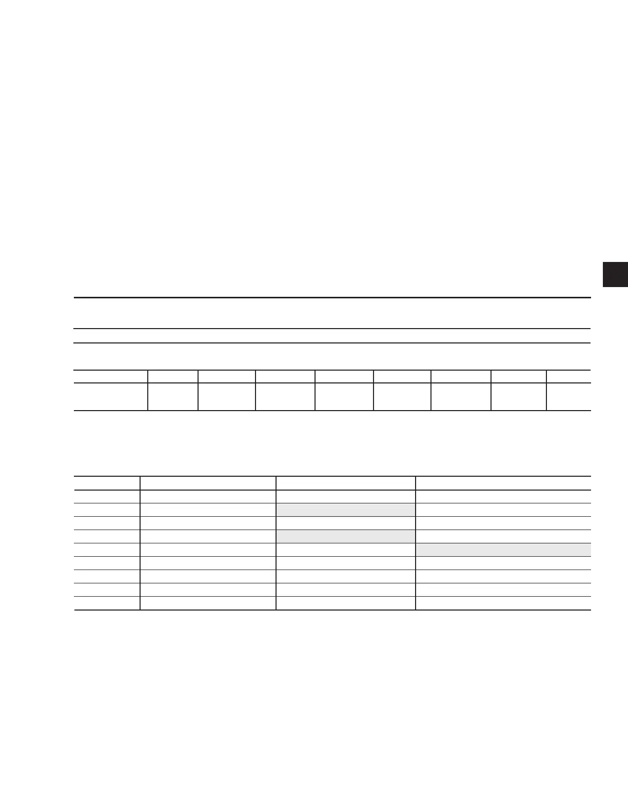
TABLE 24 – COMPRESSOR STAGING FOR RETURN WATER CONTROL
*Unloading only
COMPRESSOR STAGING FOR RETURN WATER CONTROL
6 COMPRESSORS
COOLING SETPOINT = 45°F (7.2°C) RANGE = 10°F (5.6°C)
# OF COMP ON 0 *1+HG 1 2 3 4 5 6
RWT
45°F 46.25°F 46.7°F 48.3°F 50.0°F 51.7°F 53.4°F 55.0°F
(7.2°C) (7.9°C) (8.2°C) (9.1°C) (10.0°C) (11.0°C) (11.9°C) (12.8°C)
TABLE 25 – RETURN CHILLED LIQUID CONTROL FOR 5 & 6 COMPRESSORS (7 & 8 STEPS)
*STEP COMPRESSOR COMPRESSOR ON POINT COMPRESSOR OFF POINT
0 0 SETPOINT SETPOINT
1 1 W/HGB SP + CR/8 (Note 1) SETPOINT
2 1 NO HGB SP + CR/6 SETPOINT
3 2 SP + 2*CR/6 (Note 2) SP + CR/6
4 2 SP + 2*CR/6 SP + CR/6 (Note 3)
5 3 SP + 3*CR/6 SP + 2*CR/6
6 4 SP + 4*CR/6 SP + 3*CR/6
7** 5 SP + 5*CR/6 SP + 4*CR/6
8 6 SP + CR SP + 5*CR/6
NOTES:
1. Step 1 is Hot Gas Bypass and is skipped when loading occurs. Hot Gas Bypass operation is inhibited during Pumpdown.
2. Step 3 is skipped when loading occurs.
3. Step 4 is skipped when unloading occurs.
* STEP can be viewed using the OPER DATA key and scrolling to COOLING DEMAND.
** 5-Compressor Chillers stop at 7 steps

 Loading...


