JOHNSON CONTROLS
194
FORM 150.62-NM6 (103)
INSTALLATION AND ADJUSTING INSTALLATIONS
TYPE CP MOUNTING
APPENDIX 1
Mountings are shipped completely assembled, ready
to install.
1. Locate mountings under equipment at positions
shown on tags or on VM layout drawings, or as
indicated on packing slip or correspondence.
2. Set mountings on subbase, shimming or grouting
where required to provide at and level surface at
the same elevation for all mountings (1/4" maximum
difference in elevation can be tolerated). Support
the full underside of the base plate – do not straddle
gaps or small shims.
3. Unless specied, mountings need not be fastened
to oor in any way. If required, bolt mountings to
oor through slots.
4. Set the machine or base on the mountings. The
weight of the machine will cause the upper housing
of the mount to go down, possibly resting on the
lower housing.
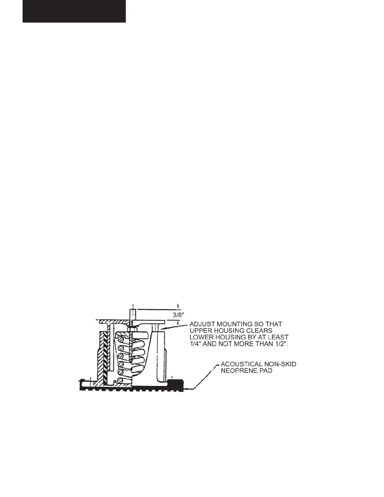
5. If clearance “X” is less than 1/4" on any mounting,
with wrench turn up one complete turn on the ad-
justing bolt of each mounting. Repeat this procedure
until 1/4", clearance at “X” is obtained on one or
more mountings.
6. Take additional turns on all mountings having less
than 1/4" clearance, until all mountings have at least
this clearance.
7. Level the machine by taking additional turns on all
mounts at the low side. Clearance should not ex-
ceed 1/2" - greater clearance indicates that mount-
ings were not all installed at the same elevation, and
shims are required. This completes adjustment.
FIG. 37 – TYPE CP MOUNTING
LD03837
Appendix 1 – Isolators

 Loading...


