JOHNSON CONTROLS
119
FORM 150.62-NM6 (103)
CHECKING INPUTS AND OUTPUTS
DIGITAL INPUTS
Refer to the unit wiring diagram. All digital inputs are con-
nected to J9 of the microboard. The term “digital” refers
to two states – either on or off. As an example, when
the ow switch is closed, 30 volts DC will be applied to
J9, pin 5 (J9-5) of the microboard. If the ow switch is
open, 0 volts DC will then be present at J9-5.
Pin 1 of J9 is an unregulated 30VDC that is the DC
voltage source used to supply the DC voltage to the
various contacts, unit switch, ow switch, etc. This DC
source is factory wired to CTB1, terminal 13. Any switch
or contact used as a digital input would be connected
to this terminal, with the other end connecting to its
respective digital input on the microboard. Any time a
switch or contact is closed, 30VDC would be applied to
that particular digital input. Any time a switch or contact
is open, 0VDC would be applied to that particular digital
input.
Typically, as high as 34VDC could be measured for the
DC voltage on the digital inputs. This voltage is in ref-
erence to ground. The unit case should be sufcient as a
reference point when measuring digital input voltages.
ANALOG INPUTS – Temperature
Refer to the unit wiring diagram. Temperature inputs are
connected to the microboard on plug J6. These analog
inputs represent varying DC signals corresponding to
varying temperatures. All voltages are in reference to
the unit case (ground). Following are the connections
for the temperature sensing inputs:
Outside Air Sensor
J6-4 = +5VDC regulated supply to sensor.
J6-7 = VDC input signal to the microboard.
See Table 37 for voltage readings that
correspond to specic outdoor temperatures.
J6-1 = drain (shield connection = 0VDC)
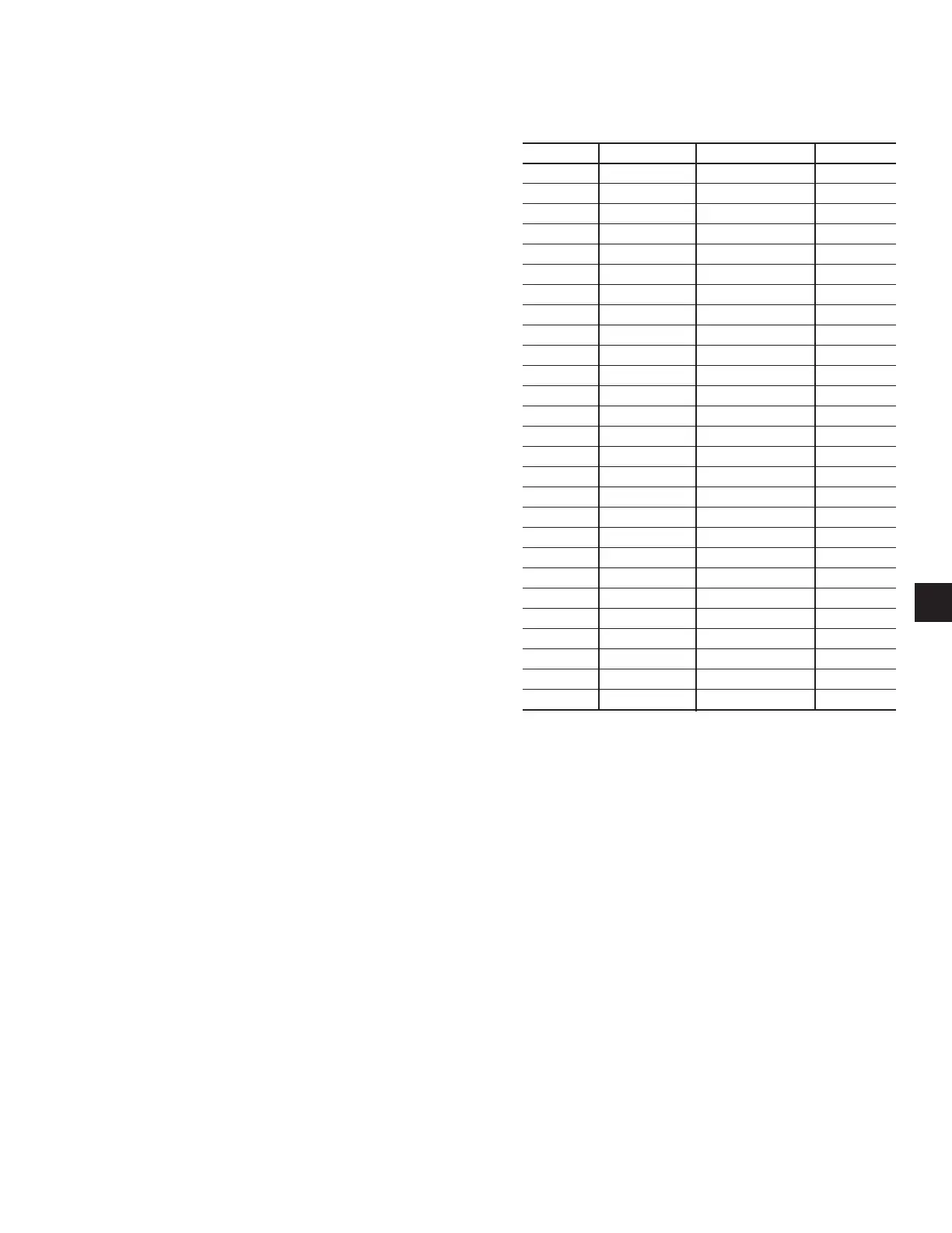
TABLE 37 – OUTDOOR AIR SENSOR
TEMPERATURE/VOLTAGE/
RESISTANCE CORRELATION
TEMP °F VOLTAGE RESISTANCE TEMP C°
0 0.7 85398 -18
5 0.8 72950 -15
10 0.9 62495 -12
15 1.0 53685 -9
20 1.1 46240 -7
25 1.2 39929 -4
30 1.4 34565 -1
35 1.5 29998 2
40 1.7 26099 4
45 1.8 22673 7
50 2.0 19900 10
55 2.2 17453 13
60 2.3 15309 16
65 2.5 13472 18
70 2.6 11881 21
75 2.8 10501 24
80 2.9 9298 27
85 3.1 8250 29
90 3.2 7332 32
95 3.4 6530 35
100 3.5 5827 38
105 3.6 5209 41
110 3.7 4665 43
115 3.8 4184 46
120 3.9 3759 49
125 4.0 3382 52
130 4.1 3048 54
3

 Loading...


