Refrigerant Connections
Units are supplied with a nitrogen holding charge. Do
not open the unit stop valves until all preparation for field
leakage checks has been completed.
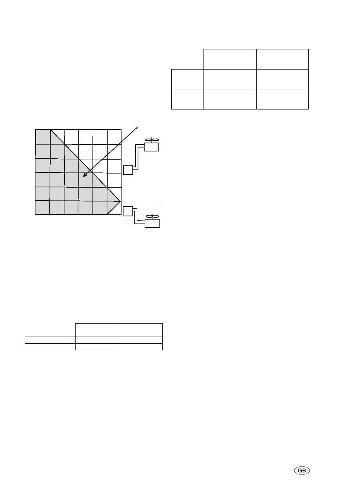
The refrigerant piping between the unit and the remote
condenser should be designed in accordance with the
following diagram.
Connection pipe sizes are given in the following table.
When selecting pipe sizes, pressure drop and velocity
must be considered. If the pipe size is too small prctical
friction loss is excessive or noise is emitted due to high
velocity. The pipe size should permit sufficient gas
speed to ensure oil return.YCRE units are equipped with
an unloader system. The diameter of the discharge
piping must allow sufficient oil to be carried even during
minimum unloader operation. An excessively large
diameter must not be selected.
YCRE units are dehydrated and and charged with
approximately 1kg of refrigerant at the factory.
It is possible that air and moisture may enter the system
during installation. It is essential that that all moisture is
removed from the piping system.
Install the connection piping and accessories with
soldered, brazed or flare connections. Install oil traps
and liquid loops in accordance with the piping
arrangement digrams. Piping length and lift must not
exceed the following values.
All horizontal discharge piping should be pitched
downwards in the direction of the refrigerant flow. The
discharge line from the compressor should be looped to
form a trap so that oil does not train from the discharge
piping to the compresssor head during compressor
stoppages.
System Testing
All newly installed pipework must be pressure/leak
tested to national code requirements (normally 1.1 x
Design Working Pressure) then fully evacuated before
charging. Refer to the Section 5 for correct charging
methods.
4-6
035-21786-100 Rev. 1 (0909)
Maximum Equivalent
Piping Length (m)
Maximum Difference
in Height (m)
Unit below
Remote
Condenser
30.0 25.0
Unit above
Remote
Condenser
30.0 5.0
Outer Diameter
(mm) Thickness (mm)
Refrigerant Gas 41.3 2.0
Refrigerant Liquid 28.6 1.6
Install piping within
limits of the shaded area
Unit
Unit
Remote
Condense
Remote
Condenser
05
L
H
5
0
5
10
15
20
25
10 15 20 25 30
H: Vertical Distance between the Chiller Unit and Remote Condenser
L: Horizontal Distance between the Chiller Unit and Remote Condenser

 Loading...


